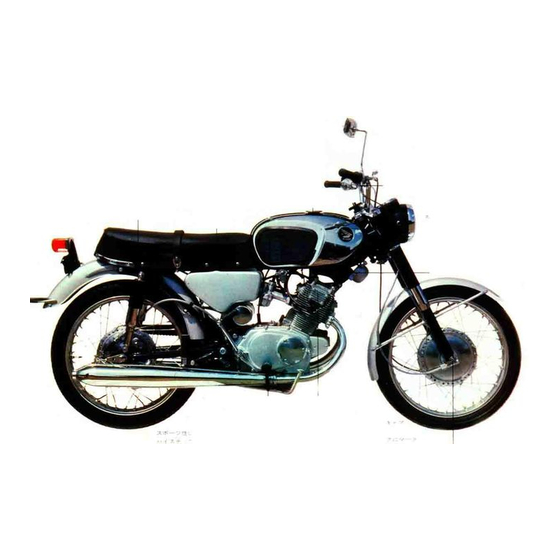
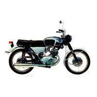
Sign In
Upload
Manuals
Brands
Honda Manuals
Motorcycle
CB160
Honda CB160 Manuals
Manuals and User Guides for Honda CB160. We have
2
Honda CB160 manuals available for free PDF download: Service Manual, Shop Manual
Honda CB160 Service Manual (138 pages)
Brand:
Honda
| Category:
Motorcycle
| Size: 7.78 MB
Table of Contents
Contents
3
Features of CB125 and 160
5
Specifications
6
Exterior Views - Front, Rear, Top and Side
10
Product View
11
Special Tools for CB125/160
12
Engine
13
Disassembling Engine
14
Footrest Arm Bolts/Pinion
14
All Wiring
14
Air Cleaner Connecting Tube
14
Clutch Cable Core
15
Removing the Drive Chain Joint
15
Removing the Starting Motor Cable
15
Removing Carburetor
15
Assembling Engine
16
Cylinder Head and Cylinder Disassembly
16
Engine Mounting Bolt
16
Installation of Engine
16
Caution Required During Disassembly and Assembly
17
Cylinder Head Cover Nuts and Bolts
17
Removing Cam Chain/Cylinder Head/Carbon
17
Description of Cylinder Head Cover and Breather
18
Cylinder Head and Cylinder Assembly
18
Installing Cam Chain
18
Handling Cam Tightener
18
Breather and Breaker Disassembly/Assembly
19
Principle of Breather
19
Removal of Breaker Point Base Plate
19
Disassembly of Spark Advance
19
Description of Camshaft
20
Camshaft Disassembly
20
Names of Cam Parts
20
Removing Rocker Arm/Camshaft
20
Camshaft Assembly
21
Description of Rocker Arm
21
Rocker Arm Disassembly/Assembly
21
Valve Rocker Arm
21
Description of Valve
22
Valve Disassembly/Installation/Seating
22
Oiling the Valve Stem
22
Dressing Valve Seat
22
Description/Inspection of Cylinder
23
Cylinder Disassembly/Assembly
23
Valve Timing Models CB 125/160
23
Coupling Piston to Cylinder
23
Construction of Left Crankcase Cover
24
Left Crankcase Cover Disassembly/Installation
24
AC Generator
24
Starter and Cable Fitted in Case Cover
24
AC Generator Disassembly/Installation
25
Operation of Starter Clutch
25
Removing AC Generator Rotor/Generator Stator
25
Example of Rotor Locating Key Set Operation
25
Operation of Clutch Adjuster
26
Disassembly and Installation of Clutch/Starter Sprocket
26
Setting Operation of Starter Clutch Roller Spring
26
Removing the Starting Sprocket Set Plate
26
Description of the Right Crankcase Cover
27
Disassembly and Assembly of Clutch Adjuster/Neutral Switch Rotor
27
Right Crankcase Cover Disassembly/Screws
27
Clutch
28
Right Crankcase Cover Installation
28
O Ring on Oil Filter Cover
28
Description and Operation of Clutch
29
Clutch Installed (Complete Vehicle)
29
Sectional View of Clutch/Clutch Adjustment Thread
29
Clutch Disassembly/Inspection
30
Removing Set Ring
30
Removing Outer Clutch and Pump Body
30
Inspection Distortion of Clutch Plate
30
Description of Oil Pump
31
Clutch Assembly
31
Fatigue of Clutch Spring
31
Measurement of Clearance of the Outer Clutch Notch and the Clutch Friction Disc
31
Lubrication Circuit
32
Oil Pump
32
Oil Pump Disassembly/Assembly
33
Removing Pump Rod/Plunger
33
Pump Parts
33
Confirming Oil Circulation
33
Operation of Oil Filter
34
Oil Filter Disassembly
34
Oil Filter Parts
34
Removing the Oil Filter Cap
34
Crankcase Description
35
Operation of Oil Separator
35
Oil Filter Assembly
35
Cleaning Oil Filter
35
Crankcase Disassembly/Assembly
36
Disassembly and Installation of Starting Motor
36
Crankcase Bolts
36
Releasing Key from Shift Drum
36
Description of Crankshaft
37
Crankshaft Disassembly
37
Crankshaft Lubricating Passage
37
Crankcase Bolts and Nuts
37
Description of Connecting Rods
38
Crankshaft Inspection/Installation
38
Measurement of Axial/Radial Clearance
38
Matching Lower Crankcase
38
Description of Pistons
39
Connecting Rods Inspection
39
Measurement of Maximum Deflection at the Piston End of Connecting Rod
39
Measurement of Parallel Condition at the Piston End of the Connecting Rod
39
Pistons Disassembly/Inspection
40
Measurement of Outside Diameter of the Piston
40
Measurement of the Ring Groove Clearance When a New Piston Ring Is Fitted
40
Removing Piston Pin Retainer
40
Description of Piston Rings
41
Pistons Assembly
41
Measurement of Piston Pin Hole
41
Measurement of the Piston Outside Diameter
41
Piston Rings Inspection/Replacing
42
Measuring Piston Ring Gap/Tension
42
Profile of Piston Ring Gap
42
Operation of Cam Chain Tightener
43
Cam Chain Tightener Disassembly
43
Inspection Piston Ring by Rotating Around the Ring Groove
43
Confirming Upper and Lower Surface of the Piston Ring
43
Cam Chain Tightener Installation/Adjustment
44
Cam Chain Guide Roller
44
Tightener Push Bar Fully Inserted
44
Adjusting a Cam Chain
44
Transmission View
45
Description of Transmission
45
Transmission System
46
Gears of Neutral Position
46
Transmission of the First/Second/Third Speed
46
Transmission Disassembly/Inspection
47
Transmission of the Fourth Speed
47
View of Transmission with Lower Crankcase Separated
47
Measuring Clearance of the Transmission Unit Bearing
47
Operation of Gear Shift
48
Transmission Assembly
48
Gear Shift Disassembly
48
After the Transmission and Crankshaft Are Coupled, the Lower Crankcase Should be Matched
48
Gear Shift Assembly
49
Removing Shift Drum Limit
49
Removing Gear Shift Spindle
49
Division of Gear Shift Fork
49
Operation of Kick Starter
50
Kick Starter Disassembly and Assembly
50
Gear Shift Drum Fork Limit
50
Assembling Kick Starter Spring
50
Description of Carburetor
51
Main/Slow Speed System
51
Sectional View of Carburetor
51
Operation of Component Parts
52
Float Chamber
52
Choke
52
Main/Air/Needle Jet
52
Jet Needle
53
Throttle Valve
53
Slow Speed Jet
53
Air Screw
53
Adjustment at High Speed/MID-Throttle
54
Replacing of Main Jet
54
Changing Step of Jet Needle
54
Adjutment at Low Speed
55
Adjustment of Standard Fuel Level
55
Adjusting Air Screw
55
Measuring Standard Fuel Level
55
Adjustment of the Throttle Opening of the Right and Left Carburetors
56
Adjusting Throttle Valve Opening
56
Construction of Handlebar
57
Handlebar Disassembly
57
Turning the Handlebar
57
Tools Required for Disassembly and Assembly
57
Handlebar Inspection/Assembly
58
Removing Handlebar/Clutch/Brake Cable
58
Adjustment of Throttle/Brake Cable Play
58
Description/Disassembly of Front Cushion
59
Adjustment of Clutch Wire Play
59
Lead Wire Clamp
59
Disassembling of Front Cushion
59
Removing Front Wheel/Fender/Speedometer
60
Front Cushion Inspection
61
Measurement of the Front Cushion Spring/Fork Piston
61
Measurement of the Outside Diameter and Bend of the Front Fork Pipe
61
Sectional View of Steering
61
Front Cushion Assembly
62
Bend/Assembly of Front Fork Pipe
62
Assembling/Installing Front Cushion
62
Construction of the Steering Stem
63
Steering Stem Disassembly
63
Tools Required for Disassembly and Assembly of Steering Stem and Handlebar Lock
63
Steering Stem Inspection/Assembly
64
Measurement of Steering Stem Bending
64
Fuel Tank
64
Tools Required for Disassembly and Assembly of Fuel Tank
64
Construction of Fuel Tank
65
Fuel Tank Disassembly
65
Remove the Tank by Using the Hose Clip
65
Fuel Tank Inspection/Assembly
66
Removing of Fuel Cock/Cock Body
66
Installing Side Cover
66
Sectional View of Side Cover Retaining Screw
66
Construction of Frame Body
67
Pushing Fuel Tank from the Rear Side
67
Frame Body Disassembly/Inspection
68
Tools Required for Disassembly and Assembly of Frame Body
68
Removing/Driving in Ball Race
68
Construction of Air Cleaner Case and Seat
69
Frame Body Assembly
69
Air Cleaner Case and Seat Disassembly/Inspection
69
Tools Required for Disassembly and Assembly of Air Cleaner Case Seat
69
Construction of Stand
70
Air Cleaner Case and Seat Assembly
70
Stand Disassembly/Inspection
70
Inspecting of the Stand Spring
70
Stand Assembly
71
Construction of the Exhaust Pipe and Muffler
71
Exhaust Pipe and Muffler Disassembly
71
Even Tightening of Muffler Steps
71
Exhaust Pipe and Muffler Inspection/Assembly
72
Muffler Mounting Bolt
72
Removing Diffuser Pipe
72
Removing Carbon with Wire Brush
72
Construction of the Air Cleaner
73
Air Cleaner Disassembly/Inspection/Assembly
73
Tools Required for Disassembly and Assembly of Air Cleaner Tool Case
73
Removing Tool Box from Frame
73
Construction of the Rear Fork
74
Rear Fork Disassembly/Inspection
74
Measurement of the Rear Fork Center Collar
74
Measurement of Rear Pivot Bushing Bore
74
Rear Fork Assembly
75
Measurement of Rear Fork Pivot Bolt
75
Measurement of Twist of the Rear Fork
75
Disassembly of Rear Fender
75
Construction of the Rear Cushion
76
Rear Cushion Disassembly/Inspection
76
Measurement of the Rear Cushion Spring
76
Tools Required for Disassembly and Assembly of Rear Cushion
76
Front Wheel
77
Rear Cushion Assembly
77
Coupling Rear Cushion
77
Description of the Front Wheel
78
Front Wheel Disassembly/Inspection
78
Measurement of Defiction and Eccentricity of the Rim
78
Tools Required for Disassembly and Assembly of the Front Wheel
78
Front Wheel Assembly
79
Measurement of the Clearance in the Axial and Radial Directions of the 6302R Ball Bearings
79
Measurement of Brake Shoe Spring
79
Measurement of the Outside Diameter and Thickness of the Front Brake Shoe
79
Insertion of Bearing
80
Angle of Gear Box Installation
80
Front Brake Wire Adjuster
80
Play of Front Brake Lever
80
Description of Rear Wheel
81
Rear Wheel Disassembly
81
Tools Required for Disassembly and Asssembly of Rear Wheel
81
Removing Drive Chain
81
Rear Wheel Inspection
82
Measurement of Deflection and Eccentricity of the Rim
82
Measurement of the Outside Diameter Bend of the Rear Wheel Axle
82
Measurement of the Tooth Bottom Diameter of the Final Driven Sprocket
82
Rear Wheel Assembly
83
Measurement of Cam Unit Thickness of Rear Brake Cam
83
Outside Diameter and Thickness Measurement of the Rear Brake Shoe
83
Rear Brake Shoe Measurement
83
Rear Brake Coupling
84
Chain Tension
84
Rear Brake Pedal Play
84
General of Electrical Parts
85
Electrical/Ignition System
85
Construction/Performance of Ignition Coil
86
Dual Side View of Ignition Coil
86
Battery Operation Coil
86
Ignition Coil Handling
87
Spark Performance Graph
87
Ignition Coil Specification/Measurement
87
Terminal Unit Covering
87
Capacitor Construction/Testing
88
Breaker Points
88
Parts of Breaker Point
89
Breaker Arm and Spring
89
Value for Maintenance and Replacement of Breaker Point
89
Contact Point Cam
90
Using Sandpaper
90
Pointed File and Oilstone
90
Correction by Oilstone
90
Spark Advancer Maintenance and Replacement
91
Graph of Spark Advancer
91
Graph of Advanced Angle of Spark Advancer
91
Spark Plug Requirements
92
Construction of Spark Plug
92
Electrode Construction
92
Spark Plug/Insulator Construction
93
Heat Characteristics of Spark Plugs
93
Favorable Status of Plug
93
Overheated/Smoke Plug
93
Necessity of Spark Plugs with Different Heat Values
94
Temperature Dissipation
94
Sectional View of Plug Characteristics
94
Plug Comparison
94
Power Source Circuit
95
AC Generator Construction
95
Specifications of AC Generator
95
AC Generator Installed on Engine
95
Performance of AC Generator
96
Silicon Rectifier
96
Measurement of Timing
96
Rectifying Operation
96
Silicon Rectifying Element
97
Rectifier of Silcon Wafer
97
Feature Comparison of Silicon and Selenium Rectifiers
98
Silicon Rectifier Mounting Section
98
Connection
98
Comparison of Silicon and Selenium Rectifiers
98
Caution Concerning Wiring
99
Specifications of the Silicon Rectifier
99
Battery Construction
100
Coupled Plate Group
100
Separator
100
Battery Charging, Discharging Ratio and Capacity
101
Battery Components
101
Graph of Specific Gravity and Electrical Capacity
101
Reversible Reaction
101
Discharge/Charge Rate
102
Initial Charge
102
Caution Required During Starting
102
Battery Without Electrolyte
102
Caution Required During Use
103
Supplementary Charge of Battery
103
Specific Gravity
103
Indication of Electrolyte Level
103
Battery Trouble/Repair
104
Anode/Negative Plate
104
Separators
104
Caution in Battery Use
104
Self-Starter
105
Starting Circuit
105
Motor Performance
105
Situation Caused Prolby Onged Discharge
105
Starter Reduction
106
Starting Motor
106
Parts of Starting Motor Reduction Mechanism
106
Starting Motor Mounted on Engine
106
Removing/Maintenance Starting Motor
107
Removing the Carbon Brush
107
Commutator
107
Starting Clutch
107
When the Starting Motor Rotates
108
When the Engine Starts
108
Lubrication
108
Caution Required During Maintenance
108
Starter Solenoid
109
Principles of Operation
109
Caution
109
Disassembly of Solenoid
109
Safety Parts
110
Circuit
110
Horn
110
Parts of Main Safety Units
110
Tail/Stop/Neutral Pilot Lamp
111
Horn Adjustment
111
Composition Lamp for Tail Lamp
111
Neutral Lamp
111
Speedometer
112
Components of the Neutral Lamp
112
Neutral Switch
112
Speedometer Assembly/Scale
112
Gear Box
113
Standard for Operating Safety
113
Principle of Speedometer
113
Replacement Values for Speedometer Repair
113
Head Lamp
114
Construction of Head Lamp
114
Principle of the Head Lamp
114
Automotive Vehicle Bulbs
115
Test Voltage
115
Inspection of Lamp Distribution
115
Combination Switches
116
Stop Switch
116
Switch Disassembly/Assembly
116
Operation and Connection of Combinatin Switch
116
Wire Harness
117
Horn Button and Dimmer Switch
117
Tips of Wires in Wire Harness
117
Fuse Box Incalled on Wire Harness
117
Maintenance
118
Engine Adjustment
118
Compression
118
Maintenance Shop
118
Tappet Adjustment
119
Correct Compression Pressure
119
Troolsequired for Tappet Clearance Adjustment
119
Alignment of the Stator
119
Ignition Timing
120
Checking Clearance with a Thickness Gauge
120
Tools Required for Adjusting the Spark Timing
120
Adjustment of Points
120
Adjusting the Spark Plugs
121
Spark Advance Arm
121
Tools Required for Spark Plug Adjustment
121
Cleaning the Spark Plugs
121
Fuel Supply
122
Carburetor Cleaning and Adjustment
122
Tools Required to Inspect the Fuel System
122
ON and RES Positions of Fuel Tank Pet Cock
122
Air Cleaner
123
Inspecting the Throttle Valve Openings with a Mirror
123
Cable Adjuster
123
Tools Required for Cleaning the Air Cleaner
123
Clutch Adjustment
124
Tools Required for Adjustment of Clutch
124
Clutch Lever Play
124
Clutch Cable Adjuster
124
Drive Chain Adjustment
125
Front Brake Adjustment
125
Tools Required for Drive Chain Adjuster/Adjustment of Front Brake
125
Drive Chain Slack
125
Rear Brake Adjustment
126
Play of the Front Brake Lever/Rear Brake Pedal
126
Adjustment of Play of Front Brake Lever
126
Tools Required for Adjusting Rear Brake
126
Battery Inspection
127
Engine Oil
127
Adjustment of Play of Rear Brake Pedal
127
Lifting the Battery from the Frame
127
Grease
128
Drain Plug
128
Oil Gauge
128
Grease Fitting on Left
128
Oiling the Drive Chain
129
Critical Connections
129
After Greasing, Replace Bearings in Hub
129
Tools for Chain Lubrication
129
Wheel Spokes
130
Daily Inspection
130
Left/Right Side Connections
130
Tightening the Spokes
130
Periodical Inspection and Repair
131
Right Side of the Vehicle
131
Honda Models CB125 and CB160 Maintenance Specifications
132
CB125 and 160 Exploded View
136
Honda Motorcycle Parts and Accessories
137
Advertisement
Honda CB160 Shop Manual (136 pages)
Brand:
Honda
| Category:
Motorcycle
| Size: 8.09 MB
Table of Contents
Table of Contents
3
Disassembling and Assembling Engine
14
Cylninder Heed and Cylinder
16
Left Crankcase Cover
24
Crankcase Cover Assembly, Right
27
Clutch
29
Oil Pump, Filter, and Separator
31
3. 7 Crankcase
35
Crankshaft, Connecting Rods, and Pistons
37
Cam Chain Tightener and Cam Chain Guide Roller
43
Transmission
45
Gear Shift
48
Kick Stater
50
Carburetor
51
Frame
57
Handlebar
57
Construction of Front Cushion
59
Steering Stem and Handlebar Lock
63
Fuel Trank
66
Frame Body
67
Air Cleaner Case and Seat
69
Stand
70
Exhaust Pipe and Muffier
71
Air Cleaner and Tool Case
73
Rear Fork and Rear Fender
74
Rear Cushion
76
Front Wheel
77
Rear Wheel
81
Velectric Equipment
85
General of Electrical Parts
85
Electrical System
85
Ignition Circuit
85
Power Source Circuit
95
Self-Starter
105
Safety Parts
115
Switch
116
Wire Harness
117
Inspection and Adjustment
118
Maintenance
119
Periodic Inspection and Repair
130
Advertisement
Related Products
Honda CB1000R
Honda CB1100NA 2017
Honda CB1000RA KO
Honda CB1000RA GS
Honda CB1000RA 2015
Honda CB125 Ace 2015
Honda CB150R 2020
Honda CB1000RA 2021
Honda CB1100EX 2018
Honda CB1000RA 2019
Honda Categories
Motorcycle
Automobile
Lawn Mower
Offroad Vehicle
Engine
More Honda Manuals
Login
Sign In
OR
Sign in with Facebook
Sign in with Google
Upload manual
Upload from disk
Upload from URL