Sign In
Upload
Manuals
Brands
Freescale Semiconductor Manuals
Computer Hardware
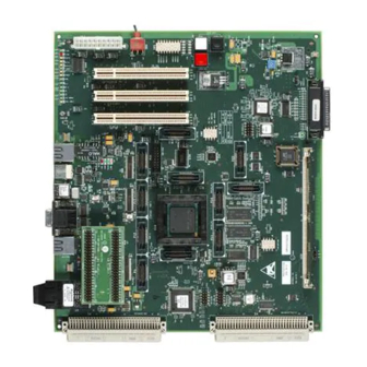
MPC8272ADS
Freescale Semiconductor MPC8272ADS Manuals
Manuals and User Guides for Freescale Semiconductor MPC8272ADS. We have
1
Freescale Semiconductor MPC8272ADS manual available for free PDF download: User Manual
Freescale Semiconductor MPC8272ADS User Manual (158 pages)
Brand:
Freescale Semiconductor
| Category:
Computer Hardware
| Size: 1 MB
Table of Contents
Table of Contents
3
MPC8272ADS Specifications
19
Overview
19
MPC8272ADS Features
20
Hardware Preparation
23
Hardware Preparation and Installation
23
Unpacking Instructions
23
Setting MODCK(1:3) for Plls Multiplication Factor-SW5 (#6-#8)
25
Setting the VDDL Supply Voltage Level
25
Setting Hard Reset Configuration Source-JP9
26
Setting Boot Source
27
Setting MODCKH(0:3) for PLL Multiplication Factors
28
Setting PCI_ARBITER for PCI Mode-Enabled
28
Setting PCI_DLL for PCI Mode-Enabled
28
Clock-In Source Selection
29
FCC1 Ethernet Port Mode-MII/RMII
29
FCC2 Ethernet Port Mode-MII/RMII
30
USB Mode Selection
30
USB Speed Selection
30
COP/JTAG Connection
31
Forced Parallel Port Connection
31
Power On/Off Switch
31
Host-Controlled Operation
33
Installation Instructions
33
Stand Alone Operation
34
COP/JTAG Connector-P21
35
Terminal to MPC8272ADS RS-232 Connection
35
10/100-Base-T Ethernet Ports Connection
36
Flash Memory SIMM Installation
36
Memory Installation
36
ABORT Switch-SW6
37
Controls and Indicators
37
Hard Reset Switches-SW6 & SW7
37
Operating Instructions
37
Power-On RESET Switch-SW3
37
Soft Reset Switch-SW7
37
3IDDL Measurement-JP1
38
Reset Configuration Switch-SW2
38
Software Options Switch-SW1
38
Thermal Sense Connector-JP7
38
IDDH Measurement-JP14
39
VPP Source Selector-JP4
39
12V Indicator-LD17
40
5-V Indicator-LD15
40
Indicator-LD14
40
Power O.K. Indicator-LD13
40
USB Power Indicator-LD5
40
UTOPIA Multi PHY Indicator-LD28
40
V Indicator-LD16
40
ATM on Indicator-LD19
41
Fast Ethernet Port 1 Enabled-LD20
41
Fast Ethernet Port 1 Full Duplex Indicator-LD1
41
Fast Ethernet Port 2 Enabled-LD22
41
RS232 Port 1 ON-LD23
41
RS232 Port 2 ON-LD24
41
RUN Indicator-LD18
41
Ethernet Port 1 LINK Indicator-LD4
42
Ethernet Port 1 Tx/Rx Indicator-LD3
42
Fast Ethernet Port 1 100Base-Tx Indicator-LD2
42
Fast Ethernet Port 2 100Base-Tx Indicator-LD7
42
Fast Ethernet Port 2 Full Duplex Indicator-LD6
42
General Purpose Led 1 Indicator-LD25
42
General Purpose Led 2 Indicator-LD26
42
USB Enabled Indicator-LD21
42
Ethernet Port 2 LINK Indicator-LD9
43
Ethernet Port 2 Tx/Rx Indicator-LD8
43
External Debugger Connection Indicator-LD11
43
Parallel Port Connection-LD10
43
VDDL Indication-LD27
43
Module Design
45
Power-On Reset
45
Power-On Reset Configuration
45
Reset and Reset Configuration
45
COP/JTAG Port Hard Reset
46
Hard Reset
46
Hard Reset Configuration
47
Internal Sources Hard Reset
47
Manual Hard Reset
47
Soft Reset
51
COP/JTAG Port Soft Reset
52
Internal Sources Soft Reset
52
Manual Soft Reset
52
PCI Bus Reset
52
ABORT Interrupt
53
ATM UNI Interrupt
53
Fast Ethernet PHY Interrupt
53
Local Interrupter
53
PCI Interrupt
53
Clock Generator
57
MPC8272 Clock
57
PCI Clock
57
Buffering
58
Bus Configuration
58
Single Powerquicc II Mode
58
Chip-Select Generator
59
Synchronous DRAM (60X Bus)
59
SDRAM Programming
60
Flash Memory SIMM
61
SDRAM Refresh
61
E2PROM Memory
63
Flash Programming Voltage
63
PCI Bus
64
ATM Port
66
Communication Ports
66
100/10 Base T Ports
67
DM9161 Control
67
Ports' Signal Description
68
RS232 Ports
68
Board Control and Status Register - BCSR
69
PC Parallel Port
69
USB Port
69
BCSR0 Board Control-Status Register 0
71
BCSR2 Board Control-Status Register 2
72
BCSR3 Board Control - Status Register 3
75
BCSR4 Board Control-Status Register 4
76
BCSR5 and BCSR7 Board Control-Status Register 3 and 5
77
COP/JTAG Port
77
Memory Map
81
Overview
81
Powerquicc II Register Programming
85
System Initialization
86
Memory Controller Register Programming
87
Physical Properties
91
Power Supply
91
5-V Rail
93
5-V Standby Rail
93
VDDH Rail
93
VDDL Bus
93
12-V Rail
94
ATX Power Connector
94
Connectors
94
Fast Ethernet Port Connectors
94
ATM 155 Port Connection
95
COP/JTAG Port Connector
95
CPM Expansion Connector
95
Logic Analyzer Connectors
95
Mach's in System Programming (ISP) Connector
95
PCI Connectors
95
RS232 Port Connector
95
Parallel Port Connector
96
PCB Layout
96
System Expansion Connector
96
USB Connector
96
Interconnect Signals
97
P13-RS232 Ports 1 and 2 Connectors
97
P10 and P23 100/10 Base-T Ethernet Port Connector
98
P21-COP/JTAG Connector
98
P1-CPM Expansion Connector
100
Logic Analyzer MICTOR Connectors
109
P26, P28, P29-PCI Connectors
109
P31 - ATX Power Supply Connector
111
P3,P4,P25-Mach/Lattice ISP Connector
112
P2-System Expansion Connector
113
P16, P19-USB Connectors
118
Programmable Logic Equations
119
U3-BCSR Code
119
U41-Power Switch Debounce
149
Appendix A Revision History
153
Index
155
Advertisement
Advertisement
Related Products
Freescale Semiconductor MPC8260 PowerQUICC II Family
Freescale Semiconductor MPC8250
Freescale Semiconductor MPC8255
Freescale Semiconductor MPC8264
Freescale Semiconductor MPC8265
Freescale Semiconductor MPC8266
Freescale Semiconductor PowerPC MPC823
Freescale Semiconductor MPC850SR
Freescale Semiconductor MPC8349EA PowerQUICC II Pro
Freescale Semiconductor PowerQUICC III MPC8555E
Freescale Semiconductor Categories
Motherboard
Computer Hardware
Microcontrollers
Control Unit
Controller
More Freescale Semiconductor Manuals
Login
Sign In
OR
Sign in with Facebook
Sign in with Google
Upload manual
Upload from disk
Upload from URL