Sign In
Upload
Manuals
Brands
Emerson Manuals
Freezer
Liebert Challenger ITR
Emerson Liebert Challenger ITR Manuals
Manuals and User Guides for Emerson Liebert Challenger ITR. We have
2
Emerson Liebert Challenger ITR manuals available for free PDF download: Technical Data Manual, Operation & Maintenance Manual
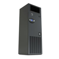
Emerson Liebert Challenger ITR Technical Data Manual (74 pages)
Row-Based, Floor-Mounted Nominal 23 or 33kW Systems, Air-Cooled, Water/Glycol-Cooled, GLYCOOL, Chilled Water, Split Systems, 50 & 60 Hz
Brand:
Emerson
| Category:
Freezer
| Size: 5 MB
Table of Contents
Liebert Challenger Itr
1
Product Nomenclature
2
Table of Contents
3
Nside Front Cover
5
1 Dedicated , Precise Environmental Control
9
Temperature Control
9
Humidity Control
9
Air Volume
9
Air Filtration
9
Year Round Operation
9
Agency Listed
9
2 Precision Environmental Control for Industrial , Telecommunications , Medical and Data Processing Equipment
10
Liebert Challenger ITR
10
Multiple Configurations to Fit a Variety of Spaces
10
Efficiency in Economic Terms
10
Glycool
10
Figure 1 Unit Configurations
11
Figure 2 Unit Configurations, Continued
12
3 Local Monitoring Systems
13
Control
13
Control Type
13
Internal System Control
13
Monitoring
13
Diagnostics
13
Logging
14
Alarms
14
Graphical Displays-Advanced Graphic Control Only
14
Figure 3 Microprocessor Control Systems
14
Figure 4 Optional Views with Advanced Graphics
14
4 Standard Features -All Systems
15
Cabinet and Frame
15
Electrical Panel
15
Fan Section
15
Infrared Humidifier
15
Electric Reheat
15
Filters
15
Condensate Pump
16
Remote Temperature/ Humidity Sensors
16
Disconnect Switch-Locking Type
16
Table 1 Condensate Pump Capacity
16
5 Chilled Water System -Standard and Optional Features
17
Chilled Water System-Standard Features
17
Cooling Coil
17
Modulating Motor
17
Line Insulation
17
Three-Way Control Valve
17
Chilled Water System-Optional Features
17
Chilled Water Flow Switch
17
High Pressure
17
6 Refrigeration Systems
18
Self-Contained Systems
18
Split Systems
18
Refrigeration System Components-Standard Features
18
Compressor
18
Evaporator Coil
18
Safety Control
18
Expansion Valve
18
7 Air -Cooled System -Standard and Optional Features
19
Air-Cooled, Self-Contained Systems-Standard Features
19
Pump down Control
19
Condenser
19
Fan Speed Control
19
Air-Cooled, Self-Contained Systems-Optional Features
19
Liebert Lee-Temp Winter Control Condenser
19
Quiet-Line Condensers
19
Figure 5 Air-Cooled Condenser with Liebert Lee-Temp
19
Air-Cooled Split Systems-Standard Features
20
Centrifugal Fan, Condensing Unit
20
Propeller Fan Condensing Unit
20
Propeller Fan Condensing Unit Options
20
Air-Cooled Split Systems-Optional Features
20
Figure 6 Outdoor Propeller Fan Condensing Unit
20
8 Water /Glycol -Cooled Systems -Standard and Optional Features
21
Water/Glycol Self-Contained Systems-Standard Features
21
Water/Glycol-Cooled, Self-Contained System-Optional Features
21
Water/Glycol Split System-Standard Features
21
Water/Glycol-Cooled, Split System-Optional Features
22
Glycol-Cooled System-Heat Rejection Devices
22
Self-Contained and Split Systems
22
9 Glycool Systems -Standard and Optional Features
23
GLYCOOL-Self-Contained Models Only
23
GLYCOOL System-Standard Features
23
Comparative Temperature Monitor
23
Econ-O-Coil
23
GLYCOOL Three-Way Control Valve
23
Glycol-Regulating Valve
23
Glycol and GLYCOOL-Cooled-Optional Equipment
24
Drycooler
24
Figure 7 Liebert Challenger ITR Unit Core
24
10 Optional Equipment -All Systems
25
Steam Generating Humidifier
25
Adjustable Floor Stand
25
Figure 8 Steam Generating Humidifier
25
Figure 9 Adjustable Floor Stand
25
SCR Reheat
26
High-Efficiency Filter
26
High External Static Blowers
26
High-Efficiency Motors
26
Plenums
26
Low-Profile Plenum with Cold-Aisle Discharge
26
Smoke Detector
27
10.10 Firestat
27
10.11 Hot Water Reheat
27
11 Comprehensive Monitoring Systems -Optional
28
Enterprise Monitoring Systems
28
Liebert Sitelink
28
Network Monitoring Systems
28
Stand-Alone Monitoring and Leak Detection Solutions
28
Figure 10 Monitoring Configurations
29
12 Comprehensive Monitoring Solutions -Optional
30
Liebert Sitescan ® Web
30
Liebert Sitelink
30
Liebert Nform
30
Liebert Intellislot Web/485 Card with Adapter and Liebert Intellislot 485 Card
30
With Adapter
30
Environmental Discrete Outputs Card
30
Remote Contact Monitor (RCM4)
30
Auto-Changeover Control
30
Universal Monitor
31
12.8.1 Leak Detection
31
12.8.2 Temperature and Humidity Recorder
31
13 System Data
32
Condensing Unit
32
Table 2 Liebert Challenger ITR Air-Cooled Data-60 Hz
32
Table
32
Table 3 Liebert Challenger ITR Air-Cooled Data-60 Hz (Continued)
33
Condensing Unit
34
Self-Contained
34
Table 4 Liebert Challenger ITR Air-Cooled Data-50 Hz
34
Table 5 Liebert Challenger ITR Air-Cooled Data-50Hz (Continued)
35
Table 6 Liebert Challenger ITR Water Cooled Data, 60 Hz
36
Table 7 Liebert Challenger ITR Water Cooled Data, 60 Hz (Continued)
37
Table 8 Liebert Challenger ITR Water Cooled Data, 50 Hz
38
Table 9 Liebert Challenger ITR Water Cooled Data, 50 Hz (Continued)
39
Table 10 Liebert Challenger ITR Glycol Cooled Data, 60 Hz
40
Indoor Unit
41
Pumps
41
Table 11 Liebert Challenger ITR Glycol Cooled Data, 60 Hz (Continued)
41
Table 12 Liebert Challenger ITR Glycol Cooled Data, 50 Hz
42
Table 13 Liebert Challenger ITR Glycol Cooled Data, 50 Hz (Continued)
43
Table 14 Liebert Challenger ITR Chilled Water Data, 60 Hz
44
Table 15 Liebert Challenger ITR Chilled Water Data, 50 Hz
45
14 Dimensional Drawings
46
Figure 11 Cabinet and Floor Planning Dimensional Data-Horizontal Flow Models
46
Figure 12 Cabinet and Floor Planning Dimensional Data
47
Figure 13 Cabinet and Floor Planning Dimensional Data-Split System-5-Ton Centrifugal Fan
47
Condensing Unit
48
Figure 14 Cabinet and Floor Planning Dimensional Data-Split System-5-Ton Water/Glycol-Cooled
48
Figure 15 Cabinet and Floor Planning Dimensional Data-Split System-Propeller Fan Condensing
49
Figure 16 Cabinet and Floor Planning Dimensional Data-Propeller Fan Condensing
50
Figure 17 Cabinet and Floor Planning Dimensional Data-Self-Contained System-Air-Cooled
50
Modules—Vertical Air Discharge
50
15 Electrical Data
51
Table 16 Liebert Challenger ITR Electrical Data 1 -60 Hz
51
Table 17 Self-Contained with SCR Reheat
52
Table 18 Scroll Compressor and Main Fan (for Comparison Purposes Only)
53
Table 19 Outdoor Condensing Units
53
Table 20 Outdoor Condensing Units-Quiet-Line
54
Table 21 Indoor Condensing Units, Air-Cooled
54
Table 22 Indoor Condensing Units, Water-Cooled
54
Table 23 Fan Speed Control Condensers
55
Table 24 Liebert Lee-Temp Condensers
55
Table 25 Liebert Lee-Temp Receiver Heater Pads for Use W/Csl Condensers
55
Table 26 Drycooler and Pump Package - 95°F (35°C) Ambient
55
Table 27 Liebert Challenger ITR Electrical Data-50 Hz
56
Table 28 Table
56
Table 30 Outdoor Condensing Units
58
Table 31 Indoor Condensing Units Air-Cooled
58
Table 32 Indoor Condensing Units Water-Cooled
58
Table 33 Fan Speed Control Condensers
58
Table 34 Liebert Lee-Temp Condensers
58
Table 35 Liebert Lee-Temp Receiver Heater Pads; for Use W/Csl Condensers
58
Table 38 Pumps
59
Table 36 Drycooler Only - 35°C (95°F) Ambient, Three-Phase
59
Table 37 Drycooler Only - 35°C (95°F) Ambient, Single Phase
59
All Systems
60
Guide
60
Specifications -Nominal 23 or 33 K W Environmental Control
60
System
60
Analog Inputs
64
Audible Alarm
64
Remote Monitoring
64
Data Collection
65
Refrigeration System
66
Comparator Circuit
68
Advertisement
Emerson Liebert Challenger ITR Operation & Maintenance Manual (72 pages)
Precision Cooling For Business-Critical Continuity
Brand:
Emerson
| Category:
Air Conditioner
| Size: 3 MB
Table of Contents
Table of Contents
3
Important Safety Instructions Save These Instructions
7
1 Introduction
9
System Descriptions
9
Compressorized Systems
9
GLYCOOL ™ (Chilled Glycol Cooling) Systems
9
Chilled Water Systems
9
2 Startup
10
Startup Procedure
10
3 Operation with Icom Control
12
Features
12
Figure 1 Liebert Icom Components
12
4 Liebert Icom Display Components and Functions
13
Table 1 Keyboard Icons and Functions
14
Navigating through the Liebert Icom Display
15
Figure 3 Liebert Icom Default Screen Symbols
15
Figure 4 Liebert Icom Default Home Screen—Graphical View
15
Control Interface-Three Main Menus
16
Figure 5 Liebert Icom Default Home Screen—Simple View
16
Accessing Menus and Settings
17
Entering the Password
17
Accessing Submenus
18
Figure 7 Menu Tree—Large and Small Displays, Stand-Alone or Networked
19
Changing Operational Settings
20
Figure 8 Liebert Icom User Menu Icons
20
Changing Liebert Icom's Display Settings
21
Figure 9 Display Setup Screen
21
Graphical Data Record
22
Liebert Icom Service Menu Icons and Legend
22
Figure 10 Temperature Graph
22
Figure 11 Liebert Icom Service Menu Icons
22
Wiring for Unit-To-Unit Communications-U2U
23
Liebert Icom U2U Ethernet Network
23
Wiring a Liebert Icom U2U Network
23
Table 2 Sample Liebert Icom Network Configurations
23
Figure 12 U2U Network Setup Diagram
25
Figure 13 Liebert Icom Wiring—Unit as Shipped
27
Figure 14 Wiring a Small Display for U2U Network Operation
28
Figure 15 Wiring a Large Display for U2U Network Operation
29
Figure 16 Liebert Icom Input-Output Control Board
30
Entering Network Setup Information
31
Figure 17 Control Board U2U Network Setup Screen
31
Figure 18 Liebert Icom Display U2U Network Setup Screen
31
Viewing Multiple Units with a Networked Large Display
32
Figure 19 Menu Tree—Large Display, Networked
32
5 Operation
33
Single Unit Functions
33
Unit/Fan Control
33
Figure 20 Start-Stop Priority Switches
33
General Compressor Requirements
34
Compressor Timing
35
Control Types
36
Proportional Control
36
PI Control
36
Intelligent Control (Chilled Water Only)
37
6 Alarm Descriptions
38
Standard Alarms
38
Change Filter
38
Compressor Overload
38
High Head Pressure
39
High Humidity
39
High Humidity and Low Humidity (Simultaneously)
39
High Temperature
39
High Temperature and Low Temperature (Simultaneously)
39
Humidifier Problem
39
Loss of Air Flow
40
6.1.10 Loss of Power
40
6.1.11 Low Humidity
40
6.1.12 Low Suction Pressure
40
6.1.13 Low Temperature
40
6.1.14 Main Fan Overload
40
6.1.15 Short Cycle
40
Optional Alarms
41
Loss of Water Flow
41
Smoke Detected
41
Standby GC Pump on
41
Standby Unit on
41
Water under Floor
41
Set Alarms-User Menus
41
Table 3 Set Alarms-User Menus
41
7 Component Operation and Maintenance
42
System Testing
42
Environmental Control Functions
42
Figure 21 Liebert Leak Detection Units
43
Figure 22 Recommended Liquid Sensor Locations
44
Table 4 Zone Leak Detection Kit Installation Scenarios
44
Filters
45
Blower Package
45
Fan Impellers and Bearings
45
Belt
45
Air Distribution
46
Refrigeration System
46
Suction Pressure
46
Table 5 Recommended Free Area Ft 2 (M 2 ) for Grilles or Perforated Panels at Output Velocities
46
Of 550 and 600 Fpm (2.8 and 3.1 M/S)
46
Table 6 Suction Pressures - R407C
46
Discharge Pressure
47
Superheat
47
Thermostatic Expansion Valve
47
Table 7 Discharge Pressures
47
Hot Gas Bypass Valve-Not Available on Digital Scroll Units
48
Air Cooled Condenser
48
Water/Glycol Cooled Condensers
49
Figure 23 Outdoor Fan/Condenser Configuration
49
Motorized Ball Valve-Digital Scroll Compressor
50
Regulating Valve-Scroll Compressor
50
Figure 24 Johnson Controls Valve Adjustment
51
Figure 25 Metrex Valve Adjustment
51
7.4.10 Drycooler Settings
52
Table 8 Water/Glycol System Conditions Requiring Optional Settings for Aquastats
52
Table 9 Aquastat Settings-Two-Fan through Four-Fan Drycoolers
52
7.4.11 Compressor Oil
53
Compressor Replacement
53
Compressor Functional Check
53
Table 10 Compressor Oil Types
53
Standard Scroll Compressor Replacement
54
Digital Scroll Compressor Replacement Procedure
55
Facility Fluid and Piping Maintenance for Water and Glycol Systems
55
Infrared Humidifier
56
Figure 26 Infrared Humidifier Lamps
57
Steam Generating Humidifier
58
Figure 27 Steam Generating Humidifier
58
Table 11 Humidifier Canister Part Numbers
60
Table 12 Blower Troubleshooting
62
Table 13 Chilled Water Troubleshooting
62
Table 14 Compressor and Refrigeration System Troubleshooting
63
Table 15 Dehumidification Troubleshooting
65
Table 16 Glycol Pump Troubleshooting
65
Table 17 Infrared Humidifier Troubleshooting
65
Table 18 Steam Generating Humidifier Troubleshooting
66
Table 19 Reheat Troubleshooting
67
M Onthly M Aintenance I Nspection C Hecklist
68
S Emiannual M Aintenance I Nspection C Hecklist
69
Advertisement
Related Products
Emerson Liebert CW
Emerson Liebert XDR
Emerson LiebertChallenger ITR
Emerson Liebert CRV
Emerson Liebert Precision Cooling
Emerson Liebert.CRV+
Emerson Liebert.CRV+ Series
Emerson Liebert PEX Series
Emerson Liebert MPH
Emerson Liebert DS/VSWS
Emerson Categories
Controller
Control Unit
Transmitter
Measuring Instruments
Fan
More Emerson Manuals
Login
Sign In
OR
Sign in with Facebook
Sign in with Google
Upload manual
Upload from disk
Upload from URL