Sign In
Upload
Manuals
Brands
Delta Electronics Manuals
Controller
VFD185F43A-G
Delta Electronics VFD185F43A-G Manuals
Manuals and User Guides for Delta Electronics VFD185F43A-G. We have
1
Delta Electronics VFD185F43A-G manual available for free PDF download: User Manual
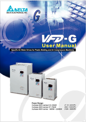
Delta Electronics VFD185F43A-G User Manual (184 pages)
VFD-G Series Specific AC Motor Drives For plastic molding and air compressors machinery
Brand:
Delta Electronics
| Category:
Controller
| Size: 4.75 MB
Table of Contents
Preface
4
Table of Contents
6
Receiving and Inspection
10
Nameplate Information
10
Model Explanation
10
Chapter 1 Introduction
10
Series Number Explanation
11
Drive Frames
11
Appearances
11
Remove Instructions
13
Remove Keypad
13
Remove Front Cover
14
Lifting
16
Preparation for Installation and Wiring
19
Ambient Conditions
19
Minimum Mounting Clearances
19
Dimensions
21
General Wiring Information
24
Chapter 2 Installation and Wiring
24
Wiring
25
Wiring for SINK Mode and SOURCE Mode
28
External Wiring
30
Main Circuit Connection
31
Mains Power Terminals
32
Output Terminals for Main Circuit
32
Terminals [+1, +2(+2/B1)] for Connecting DC Reactor
32
Control Terminals
34
Analog Inputs
35
Digital Inputs
35
Relay Outputs
35
Specification for Main Circuit Terminals and Control Terminals
37
Control Terminal
37
Power Terminal
37
Chapter 2 Installation and Wiring
37
25 HP to 40 HP
38
50 HP to 60 HP
39
75 HP to 125 HP
40
150 HP to 215 HP
41
250 HP to 300 HP
42
Wiring Explanation for Analog Input Terminal
43
Digital Keypad VFD-PU01
46
Description of the Digital Keypad
46
Chapter 3 Keypad and Start up
46
How to Operate the Digital Keypad VFD-PU01
47
VFD-PU01 Dimensions
48
Reference Table for the LED Display of the Digital Keypad
48
Operation Method
49
Trial Run
50
Chapter 4 Parameters
52
Summary of Parameter Settings
53
User Parameters
53
Chapter 4 Parameters
53
Basic Parameters
55
Operation Method Parameters
56
Output Function Parameters
58
Input Function Parameters
59
Multi-Step Speed Parameters
61
Protection Function Parameters
62
AC Drive and Motor Parameters
64
Special Parameters
65
Communication Parameters
66
Parameter Settings for Applications
69
Speed Search
69
DC Brake before Running
69
Energy Saving
69
Overheat Warning
70
Two-Wire/Three-Wire
70
Operation Command
70
Frequency Hold
70
Emergency Stop by DC Brake
71
Over-Torque Setting
71
Upper/Lower Limit Frequency
71
Skip Frequency Setting
71
Output Signal During Running
72
Output Signal in Zero Speed
72
Output Signal at Master Frequency
72
Output Signal for Over-Torque
72
Output Signal for Base Block
73
Overheat Warning for Heat Sink
73
Multi-Function Analog Output
73
Description of Parameter Settings
74
AC Drive Status Indication
75
Frequency Setting (F) or Closed Loop Control Setting Point
76
Output Frequency (H)
76
Output Current (A)
76
DC-BUS Voltage (U)
76
Maximum Output Frequency
78
Maximum Voltage Frequency (Base Frequency)
78
Maximum Output Voltage
78
MID-Point Frequency
78
MID-Point Voltage
79
Minimum Output Frequency
79
Minimum Output Voltage
79
Upper Bound Frequency
79
JOG Frequency
81
S Curve Delay Time in Accel/Decel
81
Modulation Index
81
Accel/Decel Time Unit
81
Source of Frequency Command
83
Source of Operation Command
83
Stop Method
83
PWM Carrier Frequency Selections
84
Forward/Reverse Enabled
85
2-Wire/3-Wire Operation Control Modes
85
Line Start Lockout
85
Start-Up Display Selection
86
Special Display
86
User Defined Coefficient
87
Flying Start
87
Flying Start Frequency
87
Master Frequency Memory Setting
87
Reserved
89
Master Frequency Attained
89
DC Fan Control
90
Analog Output
90
Analog Output Gain
90
Digital Input Terminal Response Time
93
Analog Input Delay
95
Summation of External Frequency Sources
95
Analog Input Frequency Gain
96
Output Frequency Gain
96
PLC Mode
97
PLC Forward/Reverse Motion
99
Time Unit Settings
102
Over-Voltage Stall Prevention
103
Over-Current Stall Prevention During Acceleration
103
Over-Current Stall Prevention During Operation
104
Over-Torque Detection Selection
105
Over-Torque Detection Level
105
Over-Torque Detection Time
105
Electronic Thermal Relay Selection
105
Low Current Detection Level
106
Low Current Detection Time
106
Low Current Detection Treatment
106
Parameter Reset
108
Parameter Protection Password Input
108
Parameter Protection Password Setting
108
Identity Code of AC Drive
109
Rated Current of AC Drive
109
Full-Load Current of Motor
109
No-Load Current of Motor
110
Auto Slip Compensation Gain
110
Rated Slip Frequency of Motor
111
Auto Torque Compensation Gain
111
Torque Compensation Gain by Manual Operation
111
DC Braking Current Level
113
DC Braking Time During Start-Up
113
DC Braking Time During Stopping
113
Start-Point for DC Braking
113
Momentary Power Loss Operation Selection
114
Maximum Allowable Power Loss Time
114
Speed Search Time
115
Maximum Speed Search Current
115
Master Frequency Command
116
Output Voltage
116
BB Speed Search Method
116
Auto Restart Times after Fault
116
Auto Restart Time after Fault
117
Automatic Energy-Saving
117
Automatic Voltage Regulation (AVR)
118
Software Setting of the Braking Level
118
Vibration Compensation Factor
119
Communication Address
120
Transmission Speed (Baud Rate)
120
Transmission Fault Treatment
120
Time-Out Detection During Transmission
120
Even/Odd Parity and Stopping Parity Setting
121
Communication Operation
121
Communication Frequency Setting
122
RTU Mode
123
Data Format
123
11-Bit Character Frame
123
Communication Protocol
124
Communication Data Frame
124
ADR (Communication Address)
125
CMD (Command Code) and DATA (Data Character)
125
RTU Mode Uses CRC
130
Address List
132
Exception Response
135
The Explanation of Exception Codes
136
PID Control Parameters
137
Input Terminal for PID Feedback
137
PID Control Detection Signal Reference
137
PID Feedback Control Method
137
Proportional Gain (P)
138
Integral Time (I)
138
Differential Time (D)
138
Upper Bound for Integral Control
138
Primary Low Pass Filter Time
139
PID Feedback Signal Range
139
PID Feedback Signal Fault Treatment Time
139
PID Feedback Signal Fault Treatment
139
V/F Curve Diagram
140
Over Current (OC)
142
Chapter 5 Troubleshooting
142
Ground Fault
143
Over Voltage (OV)
143
Low Voltage (Lv)
144
Over Heat (OH)
145
Overload
145
Keypad Display Is Abnormal
146
Phase Loss (PHL)
146
Motor Cannot Run
147
Motor Speed Cannot be Changed
148
Motor Stalls During Acceleration
149
The Motor Does Not Run as Expected
149
Electromagnetic/Induction Noise
150
Environmental Condition
150
Affecting Other Machines
151
High Harmonic at Power Side
151
Motor Temperature Rises
151
Common Problems and Solutions
152
Reset
152
Chapter 6 Fault Code Information and Maintenance
152
Maintenance and Inspections
156
Daily Inspection
156
Periodic Inspection
156
Periodical Maintenance
157
Ambient Environment
157
Voltage
157
Appendix A Specifications
162
Appendix B Accessories
164
B.1 All Brake Resistors & Brake Units Used in AC Motor Drives
164
B.2 Non-Fuse Circuit Breaker Chart
167
B.3 Fuse Specification Chart
168
460V DC Choke
169
B.4 AC Reactor
169
B.4.1 AC Input Reactor Recommended Value
169
B.4.2 AC Output Reactor Recommended Value
170
Connected in Input Circuit
171
Correct Wiring
171
B.4.3 Applications
171
B.5 Zero Phase Reactor (RF220X00A)
173
B.6.2 Explanation of Display Message
174
Description of the Digital Keypad VFD-PU06
174
Pu06
174
B.6.3 PU06 Operation Flow Chart
175
Appendix C How to Select the Right Ac Motor Drive
176
When One AC Motor Drive Operates One Motor
177
When One AC Motor Drive Operates more than One Motor
177
When It Is Running Continuously
177
Appendix C How to Select the Right AC Motor Drive
177
C.1 Capacity Formulas
177
Symbol Explanation
178
Selection Note
179
Parameter Settings Note
179
C.2 General Precaution
179
Standard Motor
180
C.3 How to Choose a Suitable Motor
180
Special Motors
181
Pole-Changing (Dahlander) Motor
181
Submersible Motor
181
Explosion-Proof (Ex) Motor
181
Power Transmission Mechanism
182
Motor Torque
182
Synchronous Motor
182
Advertisement
Advertisement
Related Products
Delta Electronics VFD185V23A/43A-2
Delta Electronics VFD1850F43A-G
Delta Electronics VFD110V43B-2
Delta Electronics VFD110V23A/43A-2
Delta Electronics VFD150V23A/43A-2
Delta Electronics VFD110F43A-G
Delta Electronics VFD150F43A-G
Delta Electronics VFD1100F43C-G
Delta Electronics VFD1320F43A-G
Delta Electronics VFD1600F43A-G
Delta Electronics Categories
Power Inductor
Power Supply
Computer Hardware
Fan
Transceiver
More Delta Electronics Manuals
Login
Sign In
OR
Sign in with Facebook
Sign in with Google
Upload manual
Upload from disk
Upload from URL