Sign In
Upload
Manuals
Brands
Dell Manuals
Server
R710 - PowerEdge - 4 GB RAM
Dell R710 - PowerEdge - 4 GB RAM Manuals
Manuals and User Guides for Dell R710 - PowerEdge - 4 GB RAM. We have
2
Dell R710 - PowerEdge - 4 GB RAM manuals available for free PDF download: Hardware Owner's Manual, Technical Manual
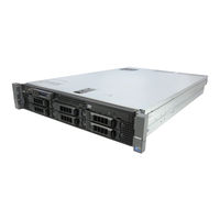
Dell R710 - PowerEdge - 4 GB RAM Hardware Owner's Manual (208 pages)
Dell Server Hardware Owner's Manual
Brand:
Dell
| Category:
Server
| Size: 5.94 MB
Table of Contents
Table of Contents
3
1 About Your System
11
Accessing System Features During Startup
11
Front-Panel Features and Indicators
12
LCD Panel Features
15
Home Screen
16
Setup Menu
16
View Menu
17
Hard-Drive Indicator Patterns for RAID
18
Back Panel Features and Indicators
19
Power Indicator Codes
21
NIC Indicator Codes
22
LCD Status Messages
23
Viewing Status Messages
23
Removing LCD Status Messages
23
System Messages
37
Warning Messages
53
Diagnostics Messages
53
Alert Messages
53
Other Information You May Need
54
2 Using the System Setup Program and UEFI Boot Manager
55
Choosing the System Boot Mode
55
Entering the System Setup Program
56
Responding to Error Messages
56
Using the System Setup Program Navigation Keys
56
System Setup Options
57
Main Screen
57
Memory Settings Screen
59
Processor Settings Screen
60
SATA Settings Screen
60
Boot Settings Screen
61
Integrated Devices Screen
62
PCI IRQ Assignments Screen
63
Serial Communication Screen
63
Embedded Server Management Screen
64
Power Management Screen
65
System Security Screen
66
Exit Screen
67
Entering the UEFI Boot Manager
68
Using the UEFI Boot Manager Navigation Keys
68
UEFI Boot Manager Screen
69
UEFI Boot Settings Screen
69
System Utilities Screen
69
System and Setup Password Features
70
Using the System Password
70
Using the Setup Password
72
Idrac Configuration Utility
73
Entering the Idrac Configuration Utility
74
3 Installing System Components
75
Recommended Tools
75
Inside the System
75
Front Bezel (Optional)
77
Removing the Front Bezel
77
Installing the Front Bezel
78
Information Tag
78
Removing the Information Tag
78
Replacing the Information Tag
78
Opening and Closing the System
79
Opening the System
79
Closing the System
79
Hard Drives
80
Mixed SAS/SATA Hard-Drive Configurations
81
Removing a Hard-Drive Blank
81
Installing a Hard-Drive Blank
82
Removing a Hot-Swap Hard Drive
82
Installing a Hot-Swap Hard Drive
83
Removing a Hard Drive from a Hard-Drive Carrier
84
Installing a Hard Drive into a Hard-Drive Carrier
84
Power Supplies
86
Removing a Power Supply
86
Replacing a Power Supply
87
Removing the Power Supply Blank
88
Installing the Power Supply Blank
88
Internal SD Module
88
Installing the Internal SD Module
88
Removing the Internal SD Module
90
Internal SD Flash Card
90
Installing the Internal SD Flash Card
90
Removing the Internal SD Flash Card
91
Internal USB Memory Key
91
Internal USB Cable
93
Removing the Internal USB Cable
93
Installing the Internal USB Cable
93
(Idrac6) Enterprise Card (Optional)
94
Installing an Idrac6 Enterprise Card
94
Removing an Idrac6 Enterprise Card
95
Vflash Media (Optional)
96
NIC Hardware Key
97
Cooling Shroud
98
Removing the Cooling Shroud
99
Installing the Cooling Shroud
100
Cooling Fans
100
Removing a Cooling Fan
100
Replacing a Cooling Fan
101
Removing the Fan Bracket
102
Replacing the Fan Bracket
103
Optical Drive
103
Removing the Optical Drive
104
Installing the Optical Drive
104
Internal Tape Backup Unit
107
Installing the Tape Backup Unit
107
Removing the Tape Backup Unit
110
Integrated Storage Controller Card
111
Removing the Integrated Storage Controller Card
112
Installing the Integrated Storage Controller Card
112
RAID Battery
116
Removing a RAID Battery
116
Storage Controller Card Cabling
116
Installing a RAID Battery
117
Cable Routing
118
Removing the Cable Retention Bracket
118
Installing the Cable Retention Bracket
119
Expansion Cards and Expansion-Card Risers
119
Expansion Card Installation Guidelines
119
Installing an Expansion Card
120
Removing an Expansion Card
122
Removing Expansion-Card Riser 1
123
Replacing Expansion-Card Riser 1
124
Removing Expansion-Card Riser 2
125
Replacing Expansion-Card Riser 2
126
Removing Expansion-Card Riser 2 from the Expansion-Card Bracket
127
Replacing the Riser 2 Board on the Expansion-Card Bracket
128
System Memory
129
General Memory Module Installation Guidelines
129
Mode-Specific Guidelines
131
Installing Memory Modules
134
Removing Memory Modules
136
Processors
137
Removing a Processor
137
Installing a Processor
140
System Battery
141
Replacing the System Battery
141
Control Panel Assembly
143
Removing the Control Panel Display Module
143
Installing the Control Panel Display Module
143
Removing the Control Panel Board
144
Installing the Control Panel Board
145
SAS Backplane
146
Removing the SAS Backplane
146
Installing a SAS Backplane
147
System Board
148
Removing the System Board
148
Installing the System Board
150
4 Troubleshooting Your System
153
Safety First-For You and Your System
153
Troubleshooting System Startup Failure
153
Troubleshooting External Connections
153
Troubleshooting the Video Subsystem
154
Troubleshooting a USB Device
154
Troubleshooting a Serial I/O Device
155
Troubleshooting a NIC
155
Troubleshooting a Wet System
156
Troubleshooting a Damaged System
157
Troubleshooting the System Battery
158
Troubleshooting Power Supplies
158
Troubleshooting System Cooling Problems
159
Troubleshooting a Fan
160
Troubleshooting System Memory
160
Troubleshooting an Internal SD Card
162
Troubleshooting an Internal USB Memory Key
163
Troubleshooting an Optical Drive
164
Troubleshooting a Tape Backup Unit
165
Troubleshooting a Hard Drive
166
Troubleshooting a Storage Controller
167
Troubleshooting Expansion Cards
168
Troubleshooting the Processor(S)
170
5 Running the System Diagnostics
173
Using Dell™ Poweredge™ Diagnostics
173
System Diagnostics Features
173
When to Use the System Diagnostics
174
Running the System Diagnostics
174
System Diagnostics Testing Options
174
Using the Custom Test Options
175
Selecting Devices for Testing
175
Selecting Diagnostics Options
175
Viewing Information and Results
176
6 Jumpers and Connectors
177
System Board Jumpers
177
System Board Connectors
180
SAS Backplane Board Connectors
182
Expansion-Card Riser-Board Components and Pcie Buses
185
Disabling a Forgotten Password
187
7 Getting Help
189
Contacting Dell
189
Glossary
191
Index
201
Advertisement
Dell R710 - PowerEdge - 4 GB RAM Technical Manual (63 pages)
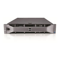
2-socket 2U rack server with the performance of Intel Xeon processors
Brand:
Dell
| Category:
Server
| Size: 1.58 MB
Table of Contents
Table of Contents
3
1 Product Comparison
7
Overview
7
Strong IT Foundation
7
Customer-Inspired Design
7
Enhanced Virtualization
7
Energy Efficient
7
Easy to Manage
8
Dell Services
8
Comparison
8
Appendix B. Additional Information and Options
8
Table 1. Feature Comparison to Poweredge R610 and R810
8
2 Key Technologies
11
Overview
11
Detailed Information
11
3 System Overview
12
Table 2. Product Features Summary
12
4 Mechanical
15
Chassis Description
15
Dimensions and Weight
15
Front Panel View and Features
15
Figure 1. Chassis Dimensions
15
Back Panel View and Features
16
Power Supply Indicators
16
Figure 2. Front View (3.5‖ Hard Drive Chassis)
16
Figure 3. Front View (2.5‖ Hard Drive Chassis)
16
Figure 4. Front View (with Optional Bezel)
16
Figure 5. Back View
16
NIC Indicators
17
Internal Chassis Views
17
Table 3. Power Supply Status
17
Rails and Cable Management
18
Readyrails Sliding Rails
18
Figure 6. Internal Chassis View
18
Readyrails Static Rails
19
Fans
19
LCD Control Panel
19
Figure 7. Fan Gantry
19
Security
20
Cover Latch
20
Bezel
20
Hard Drive
20
Figure 8. Control Panel
20
Tpm
21
Power off Security
21
Intrusion Alert
21
Secure Mode
21
USB Key
21
Battery
21
Field Replaceable Units (FRU)
21
User Accessible Jumpers, Sockets, and Connectors
21
5 Power, Thermal, Acoustic
22
Power Efficiency
22
Main Power Supply
22
Power Supply Specifications
23
Heat Dissipation
23
Environmental Specifications
23
Table 4. Power Supply Specifications
23
Table 5. Environmental Specifications
23
Figure 9. Power Supplies
23
Power Consumption Testing
24
Table 6. Power Consumption Testing
24
Maximum Input Amps
25
Energy Smart Enablement
25
Energy Star Compliance
25
Acoustics
25
Table 7. Acoustical Performance
25
6 Processors
27
Overview
27
Table 8. Intel Xeon 5500 and 5600 Processor Series Features
27
Features
28
Supported Processors
28
Table 9. Supported Processors
28
Processor Configurations
29
Single Processor Configuration
29
Processor Power Voltage Regulation Modules (EVRD 11.1)
29
Processor Installation
29
7 Memory
30
Overview
30
Dimms Supported
30
Memory Modes
30
DIMM Population Rules
31
Speed
31
Figure 10. Memory Channels
31
DIMM Slots
32
Low Voltage Dimms
32
Mirroring
32
Sparing
33
Memory Scrubbing
33
Advanced ECC (Lockstep) Mode
33
Optimizer (Independent Channel) Mode
33
Supported Configurations
33
8 Chipset
34
Overview
34
Intel I/O Hub (IOH)
34
IOH Quickpath Interconnect (QPI)
34
IOH PCI Express
34
Intel I/O Controller Hub 9 (ICH9)
34
9 Bios
36
Overview
36
Supported ACPI States
36
I 2 C (Inter-Integrated Circuit)
36
10 Embedded Nics/Lan on Motherboard (LOM)
38
11 PCI Slots
39
Overview
39
PCI Express Risers
39
Express Card Specifications (X16)
39
Quantities and Priorities
39
PCI Card Dimensions
40
12 Storage
41
Overview
41
Internal Hard Disk Drives
41
Table 10. Supported Hard Drives
41
Diskless Configuration Support
42
Hard Drive LED Indicators
42
RAID Configurations
42
Table 11. Factory RAID Configurations
42
Storage Controllers
44
SAS 6/Ir
44
PERC 6/I
44
Perc H200
44
Perc H700
45
Table 12. Storage Card Support Matrix
45
Optical Drives
46
Tape Drives
46
External Storage Support
46
13 Video
47
Table 13. Graphics Video Modes
47
14 Rack Information
48
Overview
48
Rails
48
Figure 11. R710 Sliding Rails with Optional CMA
48
Table 14. Supported Racks
49
Figure 12. 2U Threaded Rack Adapter Brackets Kit
49
Figure 13. R710 Static Rails
49
Cable Management Arm (CMA)
50
Rack View
50
Table 15. Rail Adjustability Ranges and Depth
50
Figure 14. R710 Mounted in B1 Sliding Rails
51
Figure 15. R710 Mounted in the B1 Sliding Rails with the CMA
51
Figure 16. R710 Mounted in the A2 Static Rails (2-Post Center Mount Configuration)
52
15 Operating Systems
53
16 Systems Management
54
Overview
54
Server Management
54
Embedded Server Management
55
Dell Lifecycle Controller and Unified Server Configurator
55
Integrated Dell Remote Access Controller
55
Table 16. Unified Server Configurator Features and Description
55
Idrac6 Express
56
Idrac6 Enterprise
56
Idrac6 Enterprise with Virtual Flash (Vflash) Media
56
Table 17. Features List for Base Management Functionality, Idrac, and Vflash
57
17 USB Peripherals
59
Appendix A. Certifications
60
Regulatory Certifications
60
Product Safety Certifications
60
Table 18. Product Safety Certifications
60
Electromagnetic Compatibility
61
Ergonomics, Acoustics and Hygienics
61
Table 19. Electromagnetic Compatibility Certifications
61
Table 20. Ergonomics, Acoustics and Hygienics
61
Additional Information and Options
62
Table 21. Industry Standards
62
Advertisement
Related Products
Dell POWEREDGE R710
Dell PowerEdge R715
Dell External R720 T
Dell PowerEdge R730
Dell EMC PowerEdge R740
Dell EMC PowerEdge R7515
Dell EMC PowerEdge R750xs
Dell PowerEdge R760
Dell PowerEdge R7625
Dell PowerEdge R760xa
Dell Categories
Laptop
Desktop
Server
Monitor
Storage
More Dell Manuals
Login
Sign In
OR
Sign in with Facebook
Sign in with Google
Upload manual
Upload from disk
Upload from URL