Sign In
Upload
Manuals
Brands
Daikin Manuals
Air Conditioner
VRV Plus Series
Daikin VRV Plus Series Manuals
Manuals and User Guides for Daikin VRV Plus Series. We have
3
Daikin VRV Plus Series manuals available for free PDF download: Manual, General Information Manual
Daikin VRV Plus Series Manual (413 pages)
Brand:
Daikin
| Category:
Air Conditioner
| Size: 16 MB
Table of Contents
Safety Cautions
9
Inspection after Repair
11
Using Icons
12
Using Icons List
12
Preface
13
General Information
15
Series Introduction
16
Nomenclature
16
Outdoor Unit
17
Indoor/Outdoor Unit Combinations
18
Outline of System
19
Easily Recognizable Features of the "K" Series
19
VRV System Inverter K Series System Outline
19
Changes in K Series Functions / Parts
20
Changes in the System as a Whole
20
Transmission between Outdoor Units
21
VRV System Inverter K Series
21
Changes in Indoor Units
22
Changes in Outdoor Units
22
Compatibility of Old and New VRV System Inverter
23
Functions Inverter K Series
25
Functions
26
Outdoor Unit Refrigerant System Diagram
26
Function of Thermistors and Pressure Sensors
40
List of Safety Devices and Functinal Parts Setting Values
41
Safety for Restart
42
Restart Safety Timer
42
Soft Start
42
Pump down Start
43
Heating Lay-Up Start
43
Equalized Oil Level Operation
44
Oil Return Operation
45
Compressor Operation Frequency
45
Opening of the Electronic Expansion Valve
45
Fan and Solenoid Valve
45
Defrost
46
Heating Pump down Residual Operation
47
High Pressure (Hp) Control
49
Low Pressure (Lp) Control
49
Discharge Pipe Temperature (Td) Control
49
Inverter Current Control
50
Discharge Super Heating (DSH) Control
50
Control According to Outdoor Temperature
50
Control During Low Outdoor Air Temperature Cooling
51
Low Outdoor Air Cooling in Conditions
51
Low Noise Control
53
Demand Control
54
Compressor Capacity Control
55
Te / Tc Setting
57
Gas Depletion Alarm
58
When Cooling
58
When Heating
58
Drain Pump Control
59
When the Float Switch Is Tripped During Heating Operation
60
Oil Temperature Sensor
61
Prevention of Wetness During Heating
61
Prevention of Oil Dilution During Defrost
61
Louver Control for Preventing Ceiling Dirt
62
Thermostat Sensor in Remote Controller
63
Freeze Prevention
65
Test Operation Inverter K Series
67
When Power Is Turned on
68
When Turning Power on the First Time
68
When Turning Power on after the First Time
68
Outdoor Unit PC Board Ass’y
69
Setting Modes
71
Mode Changing Procedure
71
Setting Items
73
Monitor Mode
75
Monitor Mode Data
76
Sequential Start
77
Power Supply Wiring
77
Wiring
77
External Control Adaptor for Outdoor Unit
78
System Examples
79
Switch Settings on the Adaptor PCB
79
Outdoor Unit PCB Settings
80
Cool / Heat Mode Selection
81
Low Noise / Demand Operation
86
Demand / Low Noise Input
87
Input Signal
87
Wiring Check Operation
88
Indoor Unit PCB Ass’y
89
Remote Controllers (Wired and Wireless)
90
Applicable Remote Controller Models (Wired Type)
91
Applicable Wireless Remote Controller Models
93
Control by Remote Controller
95
Indoor Field Setting
97
Wired Remote Controller
97
Wireless Remote Controller
97
Setting Contents and Code No.
98
Centralized Control Group No. Setting
99
Setting of Master Remote Controller
101
Remote Controller Self-Diagnosis Function
103
Remote Controller Service Mode
107
Model Change of Centralized Control Devices
109
When Using Model a Centralized Control Device
110
When Using Model B Centralized Control Device
111
Central Remote Controller (DCS302A51 / DCS302B61)
112
System Configuration
112
Central Remote Controller Part Names and Functions
114
Control Wiring
115
Wiring Outline
115
Contents of Control Modes
117
Unified ON/OFF Controller
119
Wiring for Transmission
120
Schedule Timer (DST301A51 / DST301B61)
122
System Configuration and Electrical Wiring
122
Schedule Timer Part Names and Functions
124
Combining Different Types of Centralized Control Devices
126
Example of DCS302A51 / DCS301A51/ DST301A51 Systems
126
Connection for Optional Controller for Centralized Control
127
Electric Wiring
128
Operation Flowcharts
133
Indoor Unit Operation Flowchart
133
Outdoor Unit Operation Flowchart
138
Diagnosis by Malfunction Code
142
Failure Diagnosis
143
Inverter Failure Diagnosis
143
Failure Diagnosis for Optional Controllers for Centralized Control
143
Troubleshooting
144
Indoor Unit: Error of External Protection Device
144
Indoor Unit: PC Board Defect
145
Indoor Unit: Malfunction of Drain Level Control System (33H)
146
Indoor Unit: Fan Motor (M1F) Lock, Overload
147
Indoor Unit: Malfunction of Swing Flap Motor (M1S)
148
Indoor Unit: Drain Level above Limit
150
Indoor Unit: Malfunction of Capacity Determination Device
150
Indoor Unit: Malfunction of Thermistor (R2T) for Liquid Pipe
151
Indoor Unit: Malfunction of Thermistor (R3T) for Gas Pipes
151
Indoor Unit: Malfunction of Thermistor (R1T) for Air Inlet
152
Indoor Unit: Malfunction of Thermostat Sensor in Remote Controller
152
Outdoor Unit: Actuation of Safety Device
153
Outdoor Unit: PC Board Defect
153
Outdoor Unit: Actuation of High Pressure Switch
154
Outdoor Unit: Actuation of Low Pressure Switch
155
Outdoor Unit: Abnormal Discharge Pipe Temperature
157
Outdoor Unit: Malfunction of Thermistor for Outdoor Air (R1T)
158
Outdoor Unit: Malfunction of Discharge Pipe Thermistor (R3T
158
Outdoor Unit: Malfunction of Thermistor (R4T) for Suction Pipe
159
Outdoor Unit: Malfunction of Thermistor (R2T) for Heat Exchanger
159
Outdoor Unit: Malfunction of Discharge Pipe Pressure Sensor
160
Outdoor Unit: Malfunction of Suction Pipe Pressure Sensor
161
Outdoor Unit: Malfunction of Oil Temperature Thermistor (R5T)
162
Negative Phase, Open Phase
164
Malfunction of Transmission between Indoor Units
165
Malfunction of Transmission between Remote Controller and Indoor Unit
166
Malfunction of Transmission between Outdoor Units
167
Excessive Number of Indoor Units
170
Address Duplication of Central Remote Controller
170
Refrigerant System Not Set, Incompatible Wiring/Piping
171
Malfunction of System, Refrigerant System Address Undefined
172
Failure Diagnosis for Inverter System
173
How to Use the Monitor Switch on the Inverter PC Board
174
Outdoor Unit: Malfunction of Inverter Radiating Fin Temperature Rise
175
Outdoor Unit: Inverter Instantaneous Over-Current
176
Outdoor Unit: Inverter Thermostat Sensor, Compressor Overload
177
Outdoor Unit: Inverter Stall Prevention, Compressor Lock
178
Power Supply Insufficient or Instantaneous Failure
180
Outdoor Unit: Inverter Over-Ripple Protection
182
PC Board Defect
184
Improper Combination of Optional Controllers for Centralized Control
185
Address Duplication, Improper Setting
186
Operation Lamp Blinks
191
Display “Under Host Computer Integrate Control” Blinks
192
Precautions When Replacing K Series PC Boards
195
Typical Wiring Mistakes
196
General Information PLUS Series
203
Features of the VRV PLUS Series
204
Improved Piping System
204
Dramatic Reduction of Wiring Saves Time and Labor When Installing
208
Less Wiring
208
System Outline
209
Heat Pump and Cooling Only System
209
Heat Recovery System
210
Indoor / Outdoor Unit Combinations
211
Heat Pump System
211
Functions PLUS Series
213
Outdoor Unit Refrigerant System Diagrams
214
List of Safety Devices and Functional Parts Setting Values
233
Outline of Control
234
Starting Control
234
Cooling Start Following Layup
235
Heating Pump down Start (for Heat Pump System)
236
Heating Power on Start (for Heat Pump System)
236
Heating Start Following Layup (for Heat Pump System)
237
Pressure Equalizing Control before Starting
238
Oil Return Control
239
Conditions for Executing Oil Control
239
Defrost (for Heat Pump System)
241
Conditions for Executing Defrost
241
Oil Equalization Control
242
Heating Pump down Residual Operation (for Heat Pump System)
246
Conditions for Pump down Residual Operation
246
Compressor Oil Temperature Protection Control
247
Low Pressure Protection Control Step
248
Low Pressure Protection Control
248
Low Pressure Protection Control (in Case of Cooling Only System)
249
High Pressure Control Step
250
Discharge Temperature Protection Control
251
Both Inverter and Standard Outdoor Units
251
Cooling Overload Control
252
Inverter Protection Control
252
Standby by Outdoor Temperature When Heating
252
Low Outdoor Temperature Control When Cooling
253
Backup Operation
257
Emergency Operation
258
Pump down Operation
262
In Case of Cooling Only System
263
Flow of Refrigerant in each Operating Mode
265
Normal Cooling
266
Normal Heating
267
Oil Return
268
Operation When Power Is Turned on
288
When Turning on Power for First Time
288
When Turning on Power the Second Time and Subsequent
288
Switch Settings According to Number of Outdoor Units
291
Functions of Pushbutton Switches
292
Mode Change
292
External Control Adaptor for Outdoor Units
301
Demand / Low Noise Control (Except for Cooling Only System)
302
Cool/Heat Mode Switching
304
Set Cool/Heat Separately for each Outdoor System by C/H SELECTOR
305
Troubleshooting for VRV PLUS Series
313
Actuation of Fin Thermal
337
Defect of Compressor Coil
338
Compressor Overload
339
Defect of Compressor
340
Power Supply Insufficient
342
Special Service Mode
345
Backup and Emergency Operation
346
Wiring Diagrams - Outdoor Unit
355
Inverter K Series - Heat Pump
357
2-Way Blow Ceiling Mounted Cassette
365
Wall Mounted Unit
375
Floor Standing Unit
376
Concealed Floor Standing Unit
377
Characteristics
378
Thermistor Resistance / Temperature Characteristics
378
Pressure Sensor Voltage Output / Detected Pressure Characteristics
380
Method of Replacing the Inverter's Power Transistors and Diode Modules
381
Method of Replacing the Inverter's Power Transistors and
381
Diode Module
382
Wiring Adaptor
383
Wiring to Outside (Host Computer Monitor Panel, Etc.)
385
Wiring Adaptor for Group Electrical Appendices
388
Part Names and Functions
388
Wiring to Outside
388
Applicable Models and Whether Mounting Box Is Required or Not
390
Adaptor for Wiring
391
Operation Display Fetch
392
Interface Adaptor for Skyair Series (DTA102A52)
393
Interface Adaptor for SKY AIR Series
394
Wiring Adaptor for Other Air Conditioners (DTA103A51)
395
Unification Adaptor for Computerized Control
401
Control Input (Unified ON/OFF Control)
402
Control Mode Switch (RS) Setting
403
Index
405
Drawings & Flow Charts
409
Advertisement
Daikin VRV Plus Series Manual (170 pages)
Brand:
Daikin
| Category:
Inverter
| Size: 5 MB
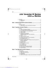
Table of Contents
Table of Contents
1
Introduction
5
Safety Cautions
5
Preface
9
Part1 General Information Inverter K Series
11
Outline
12
System Outline
12
Allowed Range of Indoor Unit and BS Unit Connection
13
Part2 Functions Inverter K Series
15
Functions
16
Outdoor Unit Refrigerant Diagrams
16
List of Safety Devices and Functional Parts Setting Values
19
Flow of Refrigerant in each Operation Mode
20
Outline of Control
25
Safety for Restart
27
Equalized Oil Level Operation (Equalized Oil Level between Twin Compressors)
29
Oil Return Operation
30
Defrost
31
Pressure Equalization Control
33
Frequency Limit Control by Pressure Equalization
34
BS Changeover Control
35
Pump down Residual Operation
36
Step down / Safety Control → Standby (Forced Thermostat OFF) → Stop Due to Malfunction
37
Low Noise Control
39
Demand Control
40
Compressor Capacity Control
41
Te / Tc Setting
42
Gas Depletion Alarm
43
Drain Pump Control
44
Louver Control for Preventing Ceiling Dirt
46
Thermostat Sensor in Remote Controller
47
Freeze Prevention
49
Part3 Test Operation Inverter K Series
51
Test Operation
52
When Power Is Turned on
52
Outdoor Unit PC Board Ass'y
53
Setting Modes
55
Monitor Mode
59
Sequential Start
61
External Control Adaptor for Outdoor Units (DTA104A61 DTA104A62)
62
External Control Adaptor for Outdoor Units (DTA104A61 TA104A62)
62
Cool/Heat Mode Switching
66
Low Noise Operation
68
Demand Control
69
Wiring Check Operation
70
Indoor Field Setting
71
Centralized Control Group No. Setting
73
Setting of Master Remote Controller
75
Remote Controller Self-Diagnosis Function
77
Operation of the Remote Controller's Inspection / Test
80
Operation of the Remote Controller's Inspection / Test Operation Button
80
Remote Controller Service Mode
81
Part 4 Troubleshooting Inverter K Series
83
Diagnosis by Malfunction Code
85
Failure Diagnosis
86
Troubleshooting
87
Indoor Unit: Error of External Protection Device
87
Indoor Unit: PC Board Defect
88
Indoor Unit: Malfunction of Drain Level Control System (33H)
89
Indoor Unit: Fan Motor (M1F) Lock, Overload
90
Indoor Unit: Malfunction of Swing Flap Motor (M1S)
91
Indoor Unit: Malfunction of Moving Part of Electronic Expansion Valve (Y1E)
92
Electronic Expansion Valve (Y1E)
92
Indoor Unit: Drain Level above Limit
93
Indoor Unit: Malfunction of Capacity Determination Device
94
Indoor Unit: Malfunction of Thermistor (R2T) for Liquid Pipe
95
Indoor Unit: Malfunction of Thermistor (R3T) for Gas Pipes
96
Indoor Unit: Malfunction of Thermistor (R1T) for Air Inlet
97
Indoor Unit: Malfunction of Thermostat Sensor in Remote Controller
98
Outdoor Unit: Actuation of Safety Device
99
Outdoor Unit: PC Board Defect
100
Outdoor Unit: Actuation of High Pressure Switch
101
Outdoor Unit: Actuation of Low Pressure Sensor
102
Outdoor Unit: Malfunction of Moving Part of Electronic Expansion Valve (Y1E)
103
Electronic Expansion Valve (Y1E)
103
Outdoor Unit: Abnormal Discharge Pipe Temperature
104
Outdoor Unit: Malfunction of Thermistor for Outdoor Air (R1T)
105
Outdoor Unit: Malfunction of Discharge Pipe Thermistor (R3T)
106
Outdoor Unit: Malfunction of Thermistor (R4T) for Suction Pipe
107
Outdoor Unit: Malfunction of Thermistor (R2T) for Heat Exchanger
108
Outdoor Unit: Malfunction of Discharge Pipe Pressure Sensor
109
Outdoor Unit: Malfunction of Suction Pipe Pressure Sensor
110
Outdoor Unit: Malfunction of Oil Temperature Thermistor (R5T)
111
Low Pressure Drop Due to Refrigerant Shortage or Electronic Expansion Valve Failure
112
Negative Phase, Open Phase
113
Malfunction of Transmission between Indoor Units
114
Malfunction of Transmission between Remote Controller and Indoor Unit
115
Malfunction of Transmission between Outdoor Units
116
Malfunction of Transmission between MAIN and SUB Remote Controllers
117
Malfunction of Transmission between Indoor and Outdoor Units in the same System
118
Excessive Number of Indoor Units
119
Address Duplication of Central Remote Controller
120
Refrigerant System Not Set, Incompatible Wiring/Piping
121
Malfunction of System, Refrigerant System Address Undefined
122
Failure Diagnosis for Inverter System
123
Points of Diagnosis
123
How to Use the Monitor Switch on the Inverter PC Board
124
Troubleshooting (Inverter)
125
Outdoor Unit: Malfunction of Inverter Radiating Fin Temperature Rise
125
Outdoor Unit: Inverter Instantaneous Over-Current
126
Outdoor Unit: Inverter Thermostat Sensor, Compressor Overload
127
Outdoor Unit: Inverter Stall Prevention, Compressor Seized
128
Outdoor Unit: Malfunction of Transmission between Inverter and Control PC Board
129
Outdor Unit: Malfunction of Transmission between Inverter and Control PC Board
129
Power Supply Insufficient or Instantaneous Failure
130
Outdoor Unit: Malfunction of Inverter Radiating Fin Temperature Rise Sensor
131
Outdoor Unit: Inverter Over-Ripple Protection
132
Troubleshooting (OP: Central Remote Controller)
133
Malfunction of Transmission between Central Remote Controller and Indoor Unit
133
PC Board Defect
134
Malfunction of Transmission between Optional Controllers for Centralized Control
135
Improper Combination of Optional Controllers for Centralized Control
136
Address Duplication, Improper Setting
137
Troubleshooting (OP: Schedule Timer)
138
Malfunction of Transmission between Central Remote Controller and Indoor Unit
138
PC Board Defect
139
Malfunction of Transmission between Optional Controllers for Centralized Control
140
Improper Combination of Optional Controllers for Centralized Control
141
Address Duplication, Improper Setting
142
Troubleshooting (OP: Unified ON/OFF Controller)
143
Operation Lamp Blinks
143
Display "Under Host Computer Integrate Control" Blinks
144
(Repeats Single Blink)
144
Display "Under Host Computer Integrate Control" Blinks (Repeats Single Blink)
144
Display "Under Host Computer Integrate Control" Blinks (Repeats Double Blink)
146
Part 5 Appendix
147
Characteristics
148
Thermistor Resistance / Temperature Characteristics
148
Pressure Sensor Voltage Output / Detected Pressure Characteristics
150
Method of Replacing the Inverter's Power Transistors and Diode Modules
151
Precaution
152
PC Boards and Remote Controller's Mode no
152
Typical Wiring Mistakes
153
Piping Diagram
160
Heat Recovery Series Outdoor Unit
160
BS Unit
161
Wiring Diagram
163
Heat Recovery Series Outdoor Unit
163
BS Unit
164
Index
165
Drawings & Flow Charts
169
Daikin VRV Plus Series General Information Manual (198 pages)
R-407C
Brand:
Daikin
| Category:
Air Conditioner
| Size: 11 MB
Table of Contents
Table of Contents
1
Part 1 General Information
5
Product Outline
6
Year 2000 Models Using New Refrigerant
6
Outline of New Series Products
7
Sie33
7
Model Configuration and Combination
9
Points to Bear in Mind at the System Design
10
Points Relating to the Performance of the Air Conditioning Units
10
The Installation Is of Vital Importance
11
Striking a Balance between System Installation and General Construction Work (Comprehensive Flow Chart)
12
Points to Bear in Mind When Preparing the Contract Drawings
13
Installation
16
Step by Step Installation Procedure
16
Work Involved in Individual Operations and Points to be Borne in Mind
17
Operational Steps
17
Selection of Location
59
Additional Refrigerant Charge Operation
81
Appendix
96
Allowable Piping Length
98
Selection of Refrigerant Pipe Size
99
Additional Charge of Refrigerant
101
REFNET Pipe Connections for VRV R-407C PLUS Series
104
Introduction
128
Cautions in Installation
129
Combination
130
Standard Operation Limit
131
Standard Supplied Accessories
132
Optional Accessories
133
Technical Specifications
134
Electrical Specifications
135
Main Components
136
Selection of Location
137
Inspecting and Handling the Unit
138
Unpacking and Placing the Unit
139
Refrigerant Piping
140
Selection of Piping Material
141
Connecting the Refrigerant Piping
142
Leak Test and Vacuum Drying
147
Pipe Insulation
148
Additional Refrigerant Charge
149
Field Wiring
151
Internal Wiring
152
Optional Parts Cool/Heat Selector
154
Power Circuit and Cable Requirements
155
General
156
Examples
157
Before Operation
162
Checks before Initial Start-Up
162
Test Run
163
Caution for Refrigerant Leaks
167
Precautions in Servicing the Models with New-Type Refrigerant
170
Tools Required
170
Notes for Work Procedures
171
Changes Required by New Refrigerants
172
Changes Required by New Refrigerant
172
Refrigerant and Refrigerant Oil Characteristics
173
Refrigerant Characteristics
173
Refrigerant Oil Characteristics
175
Refrigerant Cylinders
176
Cylinder Specifications
176
Handling of Cylinders
177
Service Tools
178
Tool Compatibility
178
New Tools Required for Hfcs and Reasons of Change
179
Cautions During Service Operations (Changes Required by New Refrigerants)
182
The Three Basic Rules for Refrigerant Piping Must be more Strictly Observed
182
Operation Guideline
183
Temperature-Pressure Conversion Table for New Refrigerants
184
Pressure and Temperature
184
Measures to Take in the Case of Gas Leaks
185
Gas Shortage
185
Measure for Gas Shortage
186
Safety Precautions
187
Problems Resulting from Negligence of Caution Items
188
Difference between Pascal and Conventional Pressure Unit
189
Comparison of Mpa and Kgf/CM²
189
Thermodynamic Characteristic Charts (HFC407C)
190
Thermodynamic Characteristics of R-407C
190
Index
193
Advertisement
Advertisement
Related Products
Daikin VRV-WIII RWEYQ26PY1
Daikin VRV4 FXDQ-M
Daikin VRVIII REYQ Series
Daikin VRV III RXYQ96PBTJ
Daikin VRV III RXYQ120PBTJ
Daikin VRV III REYQ120PBTJ
Daikin VRVIII RXYQ8P7W1B
Daikin VRV FAQ24PVJU
Daikin VRV FXDQ-A
Daikin VRV 5-S Series
Daikin Categories
Air Conditioner
Heat Pump
Chiller
Remote Control
Air Handlers
More Daikin Manuals
Login
Sign In
OR
Sign in with Facebook
Sign in with Google
Upload manual
Upload from disk
Upload from URL