Sign In
Upload
Manuals
Brands
Daewoo Manuals
Excavators
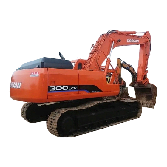
Solar 300LC-V
Daewoo Solar 300LC-V Manuals
Manuals and User Guides for Daewoo Solar 300LC-V. We have
1
Daewoo Solar 300LC-V manual available for free PDF download: Manual
Daewoo Solar 300LC-V Manual (658 pages)
Brand:
Daewoo
| Category:
Excavators
| Size: 53 MB
Table of Contents
Section 1
6
Table of Contents
6
Section 2
10
To the Operator of a Daewoo Excavator
11
General Safety Essentials
14
Location of Safety Labels
14
Summary of Safety Precautions for Lifting in Digging Mode
15
General Hazard Information
16
Unauthorized Modifications
16
Before Starting Engine
24
Machine Operation
27
Maintenance
34
Battery
42
Towing
44
Lifting with Sling
45
Shipping and Transportation
45
Section 3
50
General Description
51
Component Locations
52
Swing Motor (Toshiba MFC200)
53
Travel Motor (with Gearbox)
53
General Dimensions
55
Working Range
56
General Specifications
58
Engine Performance Curves (Per DIN 6270 Standard)
60
Approximate Weight of Workload Materials
62
Performance Tests
65
Excavator Performance Standards
66
Test Conditions
66
Travel Speed and Travel Motor Balance (Steering Deviation) Tests
66
Swing Speed and Deceleration Force Test
68
Cylinder Performance Tests
69
Section 4
74
Welding Precautions and Guidelines
75
Hydraulic System - General Precautions
76
General Precautions
77
Maintenance Service and Repair Procedure
77
Hydraulic System Cleanliness and Oil Leaks
78
Maintenance Precautions for Hydraulic System Service
78
Oil Leakage Precautions
78
Cleaning and Inspection
79
General Guidelines
79
Bearing Inspection
80
Section 5
88
Torque Values for Standard Metric Fasteners
89
Torque Values for Standard U.S. Fasteners
90
Type 8 Phosphate Coated Hardware
92
Torque Values for Hose Clamps
93
Torque Values for Split Flanges
94
Torque Multiplication
95
Torque Wrench Extension Tools
95
Other Uses for Torque Wrench Extension Tools
96
Tightening Torque Specifications (Metric)
96
Section 6
118
General Description
119
Parts List
120
Specifications
121
Removal
122
Installation
126
Section 7
130
General Description
131
Theory of Operation
131
Replacement of Rotor and Vane
132
Troubleshooting
132
Replacement of Rear Cover
133
Replacement of Armature
134
Section 8
142
General Description
143
Theory of Operation
143
Parts List
144
Specifications
145
Special Tools
146
Special Tools and Materials
146
Tool "A
146
Tool "B
146
Tool "C
147
Tool "D
147
Tool "E
147
Tool "F
148
Troubleshooting, Testing and Adjustment
149
Removal
150
Disassembly
152
Cleaning and Inspection (Wear Limits and Tolerances)
156
Reassembly
157
Installation
162
Start-Up Procedures
163
Section 9
168
General Description
169
Track Tension
169
Cleaning and Inspection (Wear Limits and Tolerances)
172
Track Removal
176
Track Shoes and Links
176
Front Idler Roller
178
Parts List
178
Front Idler Roller Disassembly
179
Front Idler Roller Reassembly
181
Lower Roller
182
Parts List
182
Lower Roller Disassembly
183
Lower Roller Removal
183
Lower Roller Installation
185
Parts List
186
Upper Roller
186
Upper Roller Reassembly
189
Parts List
191
Track Spring and Track Adjusting Cylinder
191
Section 10
196
General Description
197
Refrigerant Circulation
199
Control Panel
201
Control Specifications
202
Air Discharge According to Path Selection
204
Air-Conditioning System Circuit Diagram
206
Troubleshooting
208
Refrigerant Safe Handling Procedures
212
Refrigerant System Repairs
212
Repair and Replacement Procedure
213
Refrigerant Recovery
215
Vacuuming Refrigerant System
215
Leakage Check
216
Refrigerant Charging
217
Inspecting System for Leakage
219
Section 11
222
Drive Coupling
223
Special Tools
224
Drive Coupling Installation
226
Installation Procedure
228
Section 12
232
Hydraulic System - General Notes
234
General Notes
235
Hydraulic Schematic
235
Hydraulic Schematic (S300LC-V)
235
Boom down Circuit
236
Boom Operating Circuit
236
Operation of Working Components
236
Arm Crowd Circuit
237
Arm Dump Circuit
237
Arm Operating Circuit
237
Bucket Crowd Circuit
238
Bucket Operating Circuit
238
Swing Operating Circuit
238
Left Swing Operating Circuit
239
Right Swing Operating Circuit
239
Swing Relief Valve and Make-Up Valve
239
Travel Operating Circuit
239
Forward Travel Circuit
240
Reverse Travel Circuit
240
Initial Checks and Tests to Establish Operating Condition of the Excavator
241
Procedural Troubleshooting Baseline Recommendations
241
Adjustment and Testing
242
Pilot Pressure
242
Current Signal and Hydraulic Pressure Adjustments
243
Power Mode Valve
243
Control Valve Pressure and Current Adjustments
244
Swing Priority Valve
244
Checks and Adjustments
245
Pressure up Valve
245
Pump Input Power Control
247
Flow Meter and Flow Meter Kit Installation and Testing
251
Precautions/Initial Checks
253
Swing Relief Valve Checking and Adjustment
253
Swing System Troubleshooting
253
Troubleshooting - Swing Gearbox
255
Troubleshooting - Hydraulic Problems
256
Troubleshooting - Control Valve
258
Troubleshooting - Travel Control Valve
259
Troubleshooting - Joystick Control Valve
260
Section 13
268
General Description
269
Parts List
270
Inspection
271
Testing
271
Troubleshooting, Testing and Adjustment
271
Disassembly
272
Reassembly
273
Section 14
276
General Description
277
Theory of Operation
277
Parts List
278
Piston Nut
280
Special Tools and Materials
280
Piston Jig
284
Steel Bush Jig
288
Dust Wiper Jig
292
Slipper Seal Jig
296
Slipper Seal Straightening Jig
300
Disassembly
303
Reassembly
309
Section 15
314
General Description
316
Hydraulic Motor
316
Theory of Operation
316
Make-Up Valve Operation
318
Super Shockless Relief Valve Operation (Relief Valve Section Drawing)
319
Bypass Valve Operation (Bypass Valve Section Drawing)
320
Swing Brake Operation
321
Time Delay Valve (Time Delay Valve Section Drawing)
323
Parts List
324
Specifications
326
Pressing Tool of Inner Ring (2) and Taper Roller Bearing (4) Inner Race
327
Special Tools
327
Troubleshooting, Testing and Adjustment
328
Inspection Parts List
330
Removal
330
Disassembly
331
Disassembly of Cylinder Assembly
334
Disassembly of Lining Plates and Plates
334
Disassembly of Taper Roller Bearing Outer Race
334
Disassembly of Cylinder Assembly
335
Cleaning and Inspection (Wear Limits and Tolerances)
336
General
336
Reassembly
336
Reassembly of Cylinder Assembly
337
Reassembly of Oil Seal
338
Reassembly of Cylinder Assembly
339
Reassembly of Taper Roller Bearing Outer Race
339
Reassembly of Brake Piston
340
Reassembly of Lining Plate and Plate
340
Reassembly of O-Ring
340
Reassembly of Spring
340
Reassembly of Balance Plate
341
Reassembly of Inner Race
341
Reassembly of O-Ring
341
Applying Liquid Packing
342
Reassembly of Cover
342
Tightening of Bolt (Tightening of Cover (19) and Housing (28))
342
Confirming of Reassembly
343
Installation
343
Piping
343
Reassembly of Relief Valve Assembly, Etc
343
Hydraulic Oil
344
Preliminary Operation
344
Relief Valve
344
Start-Up Procedures
344
Section 16
346
General Description
348
Theory of Operation
349
Cause and Remedy of Trouble
367
General Caution Matters
367
Inspection Method of Abnormality of Hydraulic Motor
367
Disassembly
370
General Caution Matters
370
Reduction Gear Part
370
Disassembly of Cylinder Subassembly
375
Disassembly of Valve Casing
376
Disassembling of Drive Shaft Subassembly
377
Cleaning and Inspection (Wear Limits and Tolerances)
378
Maintenance Standard
378
Changing Standard of Hydraulic Motor Part
379
Parts Inspection and Inspection Standard of Reduction Gear
381
General Caution Matters
382
Motor Part
382
Reassembling of Drive Shaft Subassembly
382
Reassembling of Valve Casing Subassembly
382
Reassembly
382
Reassembling of Cylinder Subassembly
384
Reassembling of Motor
385
Reassembling of Angular Ball Bearing (18) of Housing (1) Part
388
Reassembling of Floating Seal (19)
390
Reassembling of Stopper (27)
390
Reassembling of Carrier Subassembly
391
Reassembling of Coupling Gear Subassembly and Housing Subassembly
391
Decision of Cluster Gear (6) Phase
392
Selection of Thrust Bearing (10) Thickness
393
Check
395
Fitting
395
Installation
395
Piping
395
Gear Oil
396
General Caution Matters
396
Kinds of Oil
396
Oil Drain
396
Oil Filling
396
Section 17
398
Swash Plate Type K5V Series Axial Piston Pump
400
Specifications
401
Construction
402
Construction and Function
402
Function
402
Cautions for Operation
404
Cautions for Piping
404
Installation
404
Cautions for Filters
405
Operational Cautions
406
Working Oil and Temperature Range
406
Cautions During Starting Operation
407
Check Pump Proper for Abnormalities
407
General Cautions
407
Oil Filling and Air Venting
407
Troubleshooting
407
Extreme Decrease of Pump Delivery Flow and Non-Increase of Delivery Pressure
408
Overload of Prime Mover
408
Abnormal Noises and Abnormal Vibrations
409
Construction of Tandem Type Duplex Pump
410
Tools
412
Axial Piston Pump Disassembling
414
Axial Piston Pump Reassembling
418
Axial Pump Maintenance Criteria
421
Correction Criteria for Cylinder, Valve Plate and Swash Plate (Shoe Plate)
421
Worn Part Replacement Criteria
421
Regulator for K5V, K3V Series of Kawasaki Swash Plate Type Axial Piston Pump
423
Type Description
423
Construction of Regulator
424
Horsepower Control
426
Outline
426
Flow Control
427
Negative Flow Control
427
Specifications
427
Variable Horsepower Control
432
Adjustment of Maximum and Minimum Flows
433
Adjustment of Maximum Flow
433
Adjustment of Minimum Flow
433
Fault Finding and Remedies on Regulator
434
Prime Mover Is Overloaded
434
Summary of Regulator Adjustment Values
434
Maximum Flow Is Not Available
435
Preparation for Disassembly
436
Tools
436
Regulator Disassembly
437
Regulator Reassembly
440
Tightening Torque
443
Section 18
446
General Description
449
When All Spools Are in Neutral
449
Signal Passage
452
Single Operation
454
Spare Spool Shifting
454
Travel Spool Shifting
454
Bucket Spool Shifting
456
Swing Spool Shifting
456
Boom Spool Shifting
458
Arm Spool Shifting
461
Parallel Orifice for Arm
464
Relief Valve
465
Combined Operation
466
Bucket Combined Operation
468
Antidrift Valve
469
Main Relief Valve
470
Overload Relief Valve (69, Total: Six Places)
471
Generation of Signal Pressure
472
Low Pressure Relief Valve (70, Total: Two Places)
472
Relief Operation
473
Parts List
474
Spool Assembly (2, Arm 2)
478
Spool Assembly (3, Boom1)
478
Spool Assembly (4, Bucket)
478
Spool Assembly (14, Arm1)
479
Spool Assembly (5, Travel)
479
Spool Assembly (6, Straight Travel)
479
Spool Assembly
480
Spool Assembly (15, Boom 2)
480
Spool Assembly (16, Swing)
480
Spool Assembly (17, Option)
480
Plug Assembly (60)
482
Relief Valve Assembly (70)
483
Specifications
483
General
484
Troubleshooting, Testing and Adjustment
484
Adjustment of Relief Valve
485
Main Relief Valve
485
Relief Valve
485
Over Load Relief Valve
486
Disassembly
487
Disassembly of Main Spool Part
487
General Instructions for Disassembly
487
Disassembly of Arm 1 para Spool Turn
488
Disassembly of Arm Regeneration Release Valve Part
489
Disassembly of Rod Check Valve Part
489
Disassembly of Antidrift Valve
490
Disassembly of Miscellaneous Plug Kind
491
Disassembly of Relief Valve
491
Disassembly of Spare Section Part
491
Disassembly of Valve Housing Combined Bolt
491
Disassembly of Main Relief Valve
492
Disassembly of Overload Relief Valve
492
Disassembly of Low Pressure Relief Valve
493
Cleaning
494
Cleaning and Inspection (Wear Limits and Tolerances)
494
Handling Instructions for Spool
494
Handling Instructions of O-Ring
494
Inspection
494
Instructions for Reassembly
494
Reassembly
494
Application Method of Loctite
495
Procedure of Subassembly
495
Reassembly of Spool Assembly (Main Spool)
495
Reassembly of Antidrift Valve Assembly
496
Reassembly of Arm 1 para Turn Spool Assembly
496
Reassembly of Load Check Valve
497
Reassembly of Relief Valve
497
Reassembly Procedure of Control Valve Body
497
Reassembly of Antidrift Valve
498
Reassembly of Arm 1 para Turn Spool
498
Reassembly of Arm Regeneration Release Valve
498
Reassembly of Spare Section Part
498
Reassembly of Main Relief Valve
499
Reassembly of Main Spool
499
Reassembly of Low Pressure Relief Valve
501
Reassembly of Overload Relief Valve
501
Installation
502
Start-Up Procedures
502
Section 19
504
Function
505
General Description
505
Theory of Operation
505
Parts List
506
Specifications
507
Torques
507
Performance
508
Removal
508
Disassembly
511
Cleaning and Inspection (Wear Limits and Tolerances)
515
Reassembly
516
Installation
521
Start-Up Procedures
522
Section 20
524
General Description
525
Pressure Reducing Valve
525
Theory of Operation
525
Operating Theory of Damper Mechanism
527
Parts List
528
Specification
529
Torque
529
Troubleshooting, Testing and Adjustment
530
Removal
531
Disassembly
533
Cleaning and Inspection (Wear Limits and Tolerances)
539
Reassembly
540
Installation
545
Start-Up Procedures
546
Electrical System
555
Section 21
556
Troubleshooting - Electrical System
558
Overview
559
Electric Supply System
560
Engine Starting Circuit
561
Engine Preheating System
563
Engine Stop System
564
Charging System
567
Monitoring System
568
Instrument Panel
569
Monitoring System Schematic
570
Instruments
572
Operation
572
Initial Operation
576
Mode Select Switch
577
Graphic Information Area Display
578
Overview
578
Main Menus for the Graphic Display Area
579
Language Setting
580
Main Menu
580
Time Setting
580
Filter/Oil Information
581
Special Menu
582
Control System Schematic
596
Electronic Hydraulic Control System (E-EPOS)
596
Power Mode Control
598
Power Mode Control - Circuit Diagram
602
Trenching Mode Control
604
Trenching Mode Control - Circuit Diagram
606
Engine Control System
607
Engine Control Motor
609
Engine Control Dial
610
Engine Control Circuit Diagram
612
Automatic Deceleration Control (Auto Idle Control)
613
Engine Overheat Protection System
614
Power Boost Mode
615
Power Boost Control - Circuit Diagram
616
Automatic Travel Speed Control
617
Automatic Travel Speed Control - Circuit Diagram
618
Engine Control Device - Adjustment
619
E-EPOS Controller
622
Self-Diagnostic Function
622
Engine Throttle Controller
624
Wiper Circuit
625
Wiper Operation
625
Wiper System
625
Window Washer Operation
626
Lighting System
628
Lighting System Circuit Diagram
628
Kind of Light
629
Overload Warning Device
630
Overload Warning Device Circuit Diagram
630
Electrical Schematic (S300LC-V)
631
Boom and Arm
639
Arm Removal Procedure
642
Front Attachment - Removal and Installation
642
Boom Removal Procedure
644
Arm Installation Procedure
645
Boom Installation Procedure
645
Installation
645
Bucket
647
Bucket Tooth Inspection and Replacement
649
Bucket O-Ring Replacement
652
New Bucket Installation
654
Attaching the Bucket
655
Bucket Attachment, Removal and Reversal
655
Detaching the Bucket
655
Reversing the Bucket
656
Advertisement
Advertisement
Related Products
Daewoo Solar 340LC-V
Daewoo Solar 330LC-V
Daewoo Solar 470LC-V
Daewoo Solar 200W-V
Daewoo Solar 225LC-V
Daewoo Solar 130LC-V
Daewoo Solar 220LC-V
Daewoo Solar 220N-V
Daewoo Solar 290LC-V
Daewoo Solar 400LC-V
Daewoo Categories
Microwave Oven
Refrigerator
Washer
TV
Vacuum Cleaner
More Daewoo Manuals
Login
Sign In
OR
Sign in with Facebook
Sign in with Google
Upload manual
Upload from disk
Upload from URL