Sign In
Upload
Manuals
Brands
Chore-Time Manuals
Farm Equipment
REVOLUTION
Chore-Time REVOLUTION Manuals
Manuals and User Guides for Chore-Time REVOLUTION. We have
1
Chore-Time REVOLUTION manual available for free PDF download: Installation And Operator's Manual
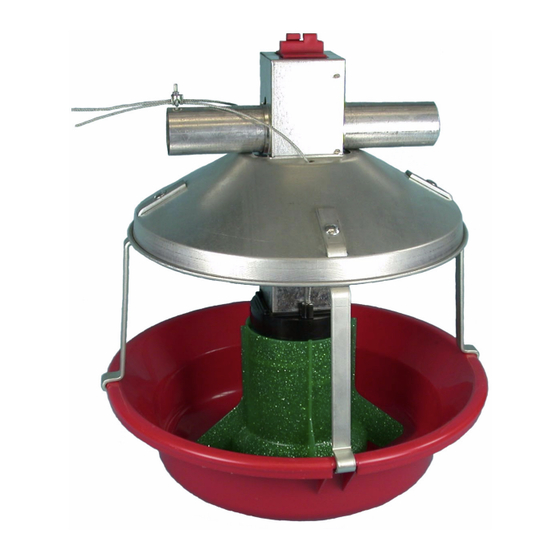
Chore-Time REVOLUTION Installation And Operator's Manual (58 pages)
Adult Turkey Feeder
Brand:
Chore-Time
| Category:
Farm Equipment
| Size: 4.35 MB
Table of Contents
Chore-Time Warranty
2
Conditions and Limitations
3
Table of Contents
4
About this Manual
6
Safety Information
6
Safety Instructions
7
Follow Safety Instructions
7
Decal Descriptions
7
General
7
Support Information
7
Model ATF Recommendations & Guidelines
8
Manufacturer's Recommendations: Birds Per Pan
9
Glossary of Terms
10
Planning the Floor Feeding System
11
Suspension System
12
Screw Hook Installation
14
Ceiling Hook Installation
15
Power Winch Installation
16
Drop Installation
16
Hopper Assembly Procedure
17
Assembly
17
Suspend the Hopper
17
Feeder Assembly
18
MODEL ATF™ Feeding System
18
Adult Turkey Feeder Assembly
19
Feeder Tube Assembly
20
Feeder Line Assembly and Suspension
21
Feeder Line Installation
21
Control Unit Installation
23
Auger Installation
25
Auger Brazing
27
Winch Adjustable Feed Level Tubes (Optional Equipment)
28
Operation
28
Installation of the Winch Adjustable Feed Level Tube System
28
Intermediate Control (Optional Equipment)
30
Intermediate Control Operation
31
Anti-Roost Installation
32
Maintaining the MODEL ATF™ Feeding System
35
Floor Feeding System Maintenance
35
Gear Head Maintenance
35
Switch Adjustment Procedure for the Control Units
36
SENSOR PLUS™ Sensor Switch Adjustment for Control Units
36
For Less Time - Turn Time Delay Adjusting Screw Counter-Clockwise (Light Blinks Fast)
36
Feeder Line
36
Power Lift Winch Maintenance
37
Trouble Shooting the MODEL ATF™ Feeding System
38
Wiring Diagrams
39
End & Intermediate Control Wiring Diagrams: Single Phase(Ø)
39
Single Phase(Ø) Wiring Diagram
39
Single Phase(Ø) Wiring Diagram W/Motor Starter
39
End & Intermediate Control Wiring Diagrams: Three Phase(Ø)
40
Three Phase(Ø) Wiring Diagram: 220/230 V
40
Three Phase(Ø) Wiring Diagram: 380/415 V
40
Sensor Plus™ Internal Wiring
41
Sensor Plus™ Control Wiring Diagram
41
Sensor Plus™ Three Phase(Ø) Wiring
42
Intermediate Control Internal Wiring
43
Parts Listing
44
150# Hopper Components
44
Hopper Mount Bracket (Optional)
45
Single Boot Components Part No. 6821
46
Twin Boot Components Part No. 8460
47
Feeder Line Components
48
Power Unit Components
49
Power Unit Assembly Part Numbers
49
Sensor Plus™ End Control Part No. 42343
50
MODEL ATF™ Control Unit Components Part No. 49040
51
Drop Tube Assembly Part No. 28072
52
Intermediate Control Part No. 6039
53
Feed Level Tube Winch Kit Part No. 46218
54
47687 Power Winch
54
Miscellaneous Suspension Components
55
MODEL ATF™ Pan Assemblies
56
Optional Parts
57
Advertisement
Advertisement
Related Products
Chore-Time REVOLUTION 8
Chore-Time REVOLUTION 12
Chore-Time Valego RDE-58
Chore-Time 40170
Chore-Time 55
Chore-Time 56471
Chore-Time 56471SS
Chore-Time 75
Chore-Time 75 Plus
Chore-Time 75 Stainless
Chore-Time Categories
Fan
Farm Equipment
Control Unit
Industrial Equipment
Controller
More Chore-Time Manuals
Login
Sign In
OR
Sign in with Facebook
Sign in with Google
Upload manual
Upload from disk
Upload from URL