Sign In
Upload
Manuals
Brands
Burkert Manuals
Controller
8635
Burkert 8635 Manuals
Manuals and User Guides for Burkert 8635. We have
5
Burkert 8635 manuals available for free PDF download: Operating Instructions Manual, Additional Instructions
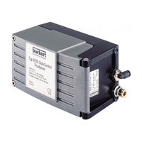
Burkert 8635 Operating Instructions Manual (190 pages)
SIDE Control Positioner
Brand:
Burkert
| Category:
Controller
| Size: 5 MB
Table of Contents
Operating Instructions for Side Control Positioner Type 8635 (S/Hart, Profibus Pa, Hart-Hand Terminal)
3
Table of Contents
3
General Notes
11
Symbols
12
General Safety Notes
12
Protection from Damage by Electrostatic Charging
13
Device-Related Notes
13
Scope of Delivery
13
Warranty Conditions
14
Master Code (S/HART)
14
System Description (S/Hart)
15
(S/Hart)
16
Construction of SIDE Control (S/HART)
16
Illustration
16
Features
17
Functional Diagram of the SIDE Control (S/HART) in Connection with a Control Valve with Single-Acting Diaphragm Actuator
18
Operation as a Positioner (S/HART)
19
Characteristics of the Positioner Software
20
Schematic Illustration of Position Control
21
Operation as a Process Controller (S/HART, Option)
22
Characteristics of the Process Controller Software (Option)
22
Schematic Illustration of Process Control
24
Interfaces (S/HART)
25
Technical Data of the SIDE Control (S/HART)
26
Technical Data (S/HART)
26
Factory Settings (S/HART)
28
System Description
16
System Description
29
(Profibus Pa)
30
Construction of SIDE Control (PROFIBUS PA)
30
Design Features
31
Options
31
Features
31
Functional Diagram of SIDE Control (PROFIBUS PA) in Connection with a Control Valve with Single-Acting Diaphragm Actuator
32
Functional Diagram of the SIDE Control (PROFIBUS PA) in Connection with a Control Valve with Single-Acting Diaphragm Actuator
32
Construction of Side Control PA (PROFIBUS PA)
30
Illustration
30
Operating as a Positioner (PROFIBUS PA)
33
Operation as a Positioner (PROFIBUS PA)
33
Characteristics of the Positioner Software
34
Schematic Illustration of Position Control
35
Interfaces (PROFIBUS PA)
36
Technical Data of SIDE Control (PROFIBUS PA)
37
Technical Data (PROFIBUS PA)
37
Technical Data of the SIDE Control (PROFIBUS PA)
37
Factory Settings (PROFIBUS PA)
38
System Description
30
Installation
39
Attachment and Assembly
40
Complete System with Bürkert Continuous Valve from Series 27Xx
40
Attachment to a Continuous Valve with Linear Actuator Acc. to NAMUR
41
Attachment to a Continuous Valve with Part-Turn Actuator
44
Fluidic Connection
46
Electrical Connection (S/HART)
47
Electrical Connection (PROFIBUS PA)
48
Inductive Proximity Switches (S/Hart, Profibus Pa, Option)
49
Description of the Inductive Proximity Switches
50
Configuration of the Adjusting Wheels (Option)
50
Settings
51
Setting with One Inductive Proximity Switch
51
Setting with Two Inductive Proximity Switches
51
Definition of the End Positions with Part-Turn Actuators
51
Operating and Controller Function
53
Operating and Controller Functions
54
Operating and Display Elements
54
Operating Levels
54
Commissioning and Set-Up as a Positioner
55
Procedure for Specifying the Basic Settings
55
Main Menu for Settings on Commissioning
57
Description of the Procedure
57
Configuring the Supplementary Functions
61
Keys in the Configuration Level
61
Configuration Menu
61
Supplementary Functions
64
Operating the Process
87
Changing between Operating Modes
87
Operating Mode AUTOMATIC (S/HART)
88
Meaning of the Keys in the Operating Mode AUTOMATIC
88
Displays in the Operating Mode AUTOMATIC
88
Operating Mode AUTOMATIC (PROFIBUS PA)
89
Meaning of the Keys in the Operating Mode AUTOMATIC
89
Displays in the Operating Mode AUTOMATIC
89
Operating Mode MANUAL
90
Meaning of the Keys in the Operating Mode MANUAL
90
Displays in the Operating Mode MANUAL
90
Operating the Process Controller (S/Hart)
91
Factory Settings of the Process Controller
92
Setting up a Process Control System
92
Supplementary Function P.CONTRL
93
Basic Settings of the Function P.CONTRL
94
Self-Parametrization for Controllers - X.TUNE
93
P.Q'LIN - Starting the Routine for Linearization of the Process Characteristic
101
Displays During Call-Up and Execution of the Routine
101
P.CO TUNE - Self-Optimization of the Process Controller (Process Tune)
102
Operation
103
Operating the Process
106
Changing between Operating Modes
106
Operating Mode AUTOMATIC
107
Meaning of the Keys in Operating Mode AUTOMATIC
107
Displays in Operating Mode AUTOMATIC
107
Manual Changing of the Process Setpoint
108
Operating Mode MANUAL
109
Meaning of the Keys in Operating Mode MANUAL
109
Displays in Operating Mode MANUAL
109
Configuration for Bus Communication (Profibus Pa)
111
GSD File
112
Setting the Device Address
115
Cyclic Parameters
115
Configuration Parameters
116
Operating Via the Hart Hand Terminal (Hart)
121
General
122
Operating Via the Hart Hand Terminal
122
System Description
123
Illustration of the System
123
Menu Description and Key Assignment
123
Data Entry
124
Commissioning
125
Preparation
125
AUTOTUNE Procedure (Required on First Commissioning)
125
Operating the Positioner Via the HART Hand Terminal
127
Changing the Process Variables
128
Operating the Positioners Via the HART Hand Terminal
127
Configuration
127
Display of the Process Variables
127
Operating the Process Controller Via the HART Hand Terminal
129
Configuration
129
Display of the Process Variables
132
Changing the Process Variables
132
Memory Organization
134
Maintenance and Error Elimination on the Positioner
135
Maintenance
135
Error Messages and Malfunctions
136
Error Messages on the LC Display
136
Other Malfunctions
137
Maintenance and Error Elimination on the Process Controller (S/Hart)
139
Error Messages and Malfunctions
139
Error Messages on the LC Display
139
Maintenance
140
Other Malfunctions
141
General Rules (Appendix)
143
Appendix General RULES
143
D Fraction
143
I Fraction
143
P Fraction
143
Superposition of P, I and D Fractions
143
Selection Criteria for Continuous Valves
144
Characteristics of PID Controllers
146
P Fraction
146
I Fraction
147
D Fraction
148
Superposition of P, I and D Fractions
149
Realized PID Controller
150
Setting Rules for PID Controllers
151
Setting Rules after Ziegler and Nichols (Oscillation Method)
151
Setting Rules after Chien, Hrones and Reswick (Output Step Method)
152
Operating Structure
155
Operating Structure of the SIDE Control (S/HART)
156
Operating Structure of the SIDE Control (PROFIBUS PA)
161
Operating Structure of the HART Hand Terminal (HART)
162
Table for Positioner
167
Tables for Process Controller S/Hart
169
Master Code S/Hart
171
Approvals S/Hart
173
Declaration of Conformity for Positioner Type 8635 SIDE Control S/HART
173
EC Design Inspection Certificate for Positioner Type 8635 SIDE Control S/HART
173
Approvals (Profibus Pa)
173
Declaration of Conformity for Positioner Type 8635 SIDE Control PA
178
EC Design Inspection Certificate for Positioner Type 8635 SIDE Control PA
178
1St Supplement
178
Approvals (S/Hart, Profibus Pa)
178
EC Design Inspection Certificate (ATEX) for Slot Initiators Types SJ
183
Inductive Proximity Switch NAMUR
183
Advertisement
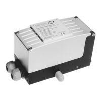
Burkert 8635 Operating Instructions Manual (166 pages)
SideControl S/HART Positioner. Fluid control systems
Brand:
Burkert
| Category:
Valve Positioners
| Size: 2 MB
Table of Contents
Deutsch
2
Table of Contents
2
Allgemeine Hinweise
6
Darstellungsmittel
7
Allgemeine Sicherheitshinweise
7
Gerätebezogene Hinweise
8
Schutz gegen Beschädigung durch Elektrostatische Aufladung
8
Lieferumfang
9
Garantiebestimmungen
9
Systembeschreibung
14
Aufbau des Sidecontrol S/HART
15
Systembeschreibung
15
Merkmale des Aufbaus
16
Funktion des Positioners Sidecontrol S/HART
17
Betrieb des Sidecontrol S/HART als Stellungsregler
18
Betrieb des Sidecontrol S/HART als Prozeßregler
18
Schnittstellen des Sidecontrol S/HART
19
Eigenschaften der Software
20
Technische Daten
21
Werkseinstellungen
21
Daten des Sidecontrol S/HART
22
Installation
24
Anbau und Montage des Sidecontrol S/HART
25
Anbau an ein Stetigventil mit Schubantrieb nach NAMUR
25
Anbau an ein Stetigventil mit Schwenkantrieb
27
Fluidischer Anschluß
29
Elektrischer Anschluß
30
Bedienung des Stellungsreglers
32
Bedien- und Anzeigeelemente
33
Bedienebenen
33
Inbetriebnahme und Einrichten als Stellungsregler
34
Grundeinstellungen
34
Werkseinstellungen
34
Werkseinstellungen des Stellungsreglers
34
Konfigurieren der Zusatzfunktionen
38
Tasten in der Konfigurierebene
38
Konfiguriermenü
38
Zusatzfunktionen
40
Bedienung des Prozesses
54
Betriebszustand AUTOMATIK
55
Betriebszustand HAND
56
Bedienung des Prozessreglers
58
Einrichten einer Prozeßregelung
59
Bedienung des Prozesses
68
Betriebszustand AUTOMATIK
69
Manuelles Verändern des Prozeßsollwerts
70
Betriebszustand HAND
71
Wartung des Stellungsreglers
72
Wartung
72
Fehlermeldungen auf dem LC-Display
73
Fehlermeldung Beim Einschalten
73
Fehlermeldungen bei der Durchführung der Funktion X.TUNE
73
Sonstige Störungen
73
Wartung des Prozessreglers
74
Wartung
74
Fehlermeldungen auf dem LC-Display
75
Fehlermeldung Beim Einschalten
75
Fehlermeldungen bei der Durchführung der Funktion X.TUNE
75
Fehlermeldung bei der Durchführung der Funktion P.Q'LIN
75
Sonstige Störungen
75
English
84
General Notes
90
Device-Related Notes
90
Protection from Damage by Electrostatic Charging
90
Scope of Delivery
91
Warranty Conditions
91
System Description
97
Construction of the Sidecontrol S/HART
97
Design Features
98
Function of the Sidecontrol S/HART Positioner
99
Operation of the Sidecontrol S/HART as a Positioner
100
Operation of the Sidecontrol S/HART as a Process Controller
100
Interfaces of the Sidecontrol S/HART
101
Software Characteristics
102
Technical Data
103
Works Settings
103
Data of the Sidecontrol S/HART
104
Installation
106
Attachment and Assembly of the Sidecontrol S/HART
107
Attachment to a Continuous Valve with Linear Actuator Acc. to NAMUR
107
Attachment to a Continuous Valve with Part-Turn Actuator
109
Fluidic Connection
111
Electrical Connection
112
Setting up a Process Control System
141
Supplementary Function P.CONTRL
143
Operating the Process
150
Operating Mode AUTOMATIC
150
Manual Changing of the Process Set Point
152
Operating Mode MANUAL
153
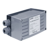
Burkert 8635 Operating Instructions Manual (105 pages)
Electropneumatic positioner
Brand:
Burkert
| Category:
Valve Positioners
| Size: 4 MB
Table of Contents
Table of Contents
3
1 Operating Instructions
6
Symbols
6
Definition of Terms
6
2 Intended Use
7
3 Basic Safety Instructions
8
4 General Notes
9
Contact Addresses
9
Warranty
9
Master Code
9
Information on the Internet
9
5 Product Description
10
Product Variants
11
Options
12
Functional Diagram
13
Interfaces
14
Operation as Positioner
15
Operation as a Process Controller (Option)
16
6 Technical Data
18
Conformity
18
Standards
18
Type Label
18
Operating Conditions
19
Safety End Positions after Failure of the Electrical or Pneumatic Auxiliary Power
21
7 Direct Attachment to Bürkert Control Valves
22
8 Installation of the Remote Variant
23
Wall Mounting with Mounting Bracket
24
Position Sensor Remote" Attachment Kit
25
Mounting the Position Sensor on the Actuator
26
Connecting the Position Sensor Electrically
27
Connecting the Position Sensor Pneumatically
28
9 Direct Attachment of the Linear Actuator
29
Attachment Kit for Linear Actuators
30
Mounting the Hoop and Lever
31
Attaching the Mounting Bracket
32
Aligning the Lever Mechanism
34
10 Direct Attachment to the Rotary Actuator
35
Attachment Kit For Rotary Actuators
35
Mounting The Sidecontrol On The Rotary Actuator
36
11 Pneumatic Connection
38
12 Electrical Connection
39
13 Operating and Display Elements
41
Assignment Of The Keys
41
14 Operating Levels
42
15 Operating States
43
Changing The Operating State
43
Detecting The Operating State
43
16 Automatic Operating State During Position Control
44
Meaning Of The Keys
44
Displays In Automatic Operating State
44
17 Automatic Operating State During Process Control
45
Meaning Of The Keys
45
Displays In Automatic Operating State
45
18 Basic Functions and Auxiliary Functions
47
Main Menu With The Basic Functions
47
Function Of The Keys In The Main Menu And Addfunct
47
Auxiliary Functions That Can Be Enabled
48
Factory Settings Of The Auxiliary Functions
49
Enabling And Disabling Auxiliary Functions
50
Setting Numerical Values
51
Overview Of The Auxiliary Functions
52
19 Description of the Auxiliary Functions
53
Charact: Selecting The Characteristic Type
53
Cutoff: Sealing Function
56
Dir.CMD: Effective Direction Of The Set-Point Value For Setting The Valve Position
57
19.4 DIR.ACT: Setting the Effective Direction of the Pressurisation State of the Actuator to the Actual Position
58
Spltrng: Splitting The Standard Signal Range
59
X.limit: Limiting The Mechanical Stroke Range
60
X.time: Reducing The Control Speed
61
X.contrl Parameterising The Position Control
62
P.contrl: Parameterising The Process Control
63
P.q'lin: Linearisation Of The Process Characteristic
67
Code: Code Protection For Settings
68
Safepos Setting The Safety Position
69
SIG-Err Configuring The Signal Error Detection
70
BIN-In: Setting The Function Of The Digital Input
71
Output: Configuring Outputs (Option)
72
Cal.user: Changes To The Factory Calibration Through The User
75
Set.fact: Factory Reset
76
20 Start-Up as Positioner
77
Carry Out The X.tune Function (Autotune)
78
X.tune Function - Manual Tune
80
21 Start-Up as Process Controller
82
Sequence Of The Work Steps
82
P.tune: Carrying Out Self-Optimisation Of The Process Controller
83
Manual Changing Of The Process Set-Point Value
86
22 Maintenance and Troubleshooting
87
Maintenance
87
Error Messages, Position Control
87
Error Messages, Process Control
89
23 Accessories
90
24 Packaging, Transport
91
25 Storage
91
26 Disposal
91
27 Additional Information
92
Selection Criteria For Control Valves
92
Properties Of Pid Controllers
94
Rules For Adjusting Pid Controllers
99
28 Menu Structure of the Software
103
29 Appendix
104
Settings Of The Freely Programmable Characteristic
104
Set Process Control Parameters
105
Advertisement
Burkert 8635 Additional Instructions (22 pages)
Electropneumatic positioner with ATEX approval
Brand:
Burkert
| Category:
Valve Positioners
| Size: 0 MB
Table of Contents
English
3
Table of Contents
3
Additional Instructions
3
Definition of Terms / Abbreviation
3
Symbols
4
Authorized Use
4
Particular Safety Instructions
5
Explosion Protection Approval
6
Instructions on Operation in an Explosion-Risk (Ex) Area
6
Deutsch
9
Begriffsdefinition / Abkürzung
9
Zusatzanleitung
9
Bestimmungsgemässe Verwendung
10
Darstellungsmittel
10
Besondere Sicherheitshinweise
11
Ex-Zulassung
12
Hinweise für den Einsatz IM Ex-Bereich
12
Français
15
Able de Matières 1 Instruction Supplémentaire
15
Définition du Terme / Abréviation
15
Symboles
16
Utilisation Conforme
16
Consignes De Sécurité Spécifiques
17
Homologation Ex
18
Consignes Pour L'utilisation en Zone Ex
18
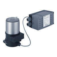
Burkert 8635 Additional Instructions (12 pages)
Remote-Positioner, Installation on process valves with internal air flow
Brand:
Burkert
| Category:
Valve Positioners
| Size: 0 MB
Table of Contents
1 Additional Instructions
2
Table of Contents
2
Symbols
2
2 Remote Operation
3
3 Assembling the Position Sensor
4
Installing Attachment Kit on the Actuator
4
Mounting Remote Position Sensor on the Actuator
5
Pneumatic Connection of the Position Sensor
7
Electrical Connection of the Position Sensor
8
4 Start-Up
9
5 Removal
10
Removing the Position Sensor
10
6 Transportation, Storage, Disposal
11
Advertisement
Related Products
Burkert 8681
Burkert 8644 AirLINE
Burkert 8623-B
Burkert 8624
Burkert 8624-B
Burkert 8605 KK
Burkert 8630
Burkert 8631
Burkert 8694
Burkert 8685
Burkert Categories
Control Unit
Controller
Measuring Instruments
Transmitter
Accessories
More Burkert Manuals
Login
Sign In
OR
Sign in with Facebook
Sign in with Google
Upload manual
Upload from disk
Upload from URL