Sign In
Upload
Manuals
Brands
Bryant Manuals
Air Conditioner
589A
Bryant 589A Manuals
Manuals and User Guides for Bryant 589A. We have
1
Bryant 589A manual available for free PDF download: Installation, Start-Up And Service Instructions Manual
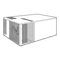
Bryant 589A Installation, Start-Up And Service Instructions Manual (53 pages)
SINGLE PACKAGE GAS HEATING/ ELECTRIC COOLING UNITS
Brand:
Bryant
| Category:
Air Conditioner
| Size: 1.89 MB
Table of Contents
Safety Considerations
1
Table of Contents
1
Unit 589A Shown with Optional Base Rail
1
588A018-042 Without Base Rail, Unit Dimensions
2
Front View
2
Left Side View
2
Rear View
2
588A018-042 with Optional Base Rail, Unit Dimensions
3
588A048,060 Without Base Rail, Unit Dimensions
4
588A048,060 with Optional Base Rail, Unit Dimensions
5
589A024-036 Without Base Rail, Unit Dimensions
6
589A024-036 with Optional Base Rail, Unit Dimension
7
589A042-060 Without Base Rail, Unit Dimensions
8
589A042-060 with Optional Base Rail, Unit Dimensions
9
General
1
Receiving and Installation
10
Step 1 - Check Equipment
10
Step 2 - Provide Unit Support
10
Step 3 - Field Fabricate Ductwork
10
Step 4 - Provide Clearances
10
Step 5 - Rig and Place Unit
10
Roof Curb Dimensions
11
Notice to Riggers
12
Slab Mounting Details
12
Suggested Rigging for Units with Optional Base Rail
12
Suggested Rigging for Units Without Base Rail
12
Condensate Trap
13
Step 6 - Connect Condensate Drain
13
Step 7 - Install Flue Hood
13
Step 8 - Install Gas Piping
13
Physical Data — Unit 588A
14
Physical Data — Unit 589A
15
Configuring Units for Downflow (Vertical) Discharge
16
Sediment Trap
16
Step 9 - Install Duct Connections
16
Lance Location for Vertical Duct Opening Cover
17
Maximum Gas Flow Capacity
17
Supply and Return Duct Openings
17
Vertical Duct Cover Removed
17
High-Voltage Connections
18
Standard Power Entry
18
Step 10 - Install Electrical Connections
18
Vertical Discharge Cover Removed
18
Electrical Data — Unit 588A
19
Legend
19
Electrical Data — Unit 589A
20
Alternate Connection
21
Alternate Power Entry
21
High- and Control-Voltage Connections
21
Standard Connection
21
Easy Select Interface Board
22
Heat Anticipator Setting
22
Pre-Start-Up
22
Transformer Protection
22
Check for Refrigerant Leaks
23
Start up Heating Section and Make Adjustments
23
Adjust Gas Input
23
Check Gas Input
23
Burner Assembly
24
Measure Gas Flow (Natural Gas Units)
24
Rated Gas Inputs at Indicated Manifold Pressures
24
Air Delivery (Cfm) at Indicated Temperature Rise /Rated Heating Input
25
Check Burner Flame
25
Measure Manifold Pressure (Propane Units)
25
Monoport Burners
25
Checking Cooling Control Operation
26
Heating Sequence of Operation
26
LED Indications
26
Start up Cooling Section and Make Adjustments
26
208/230-1-60 Wiring Diagram, Units 588A018-060
27
208/230-3-60 Wiring Diagram, Units 588A030-060
28
460-3-60 Wiring Diagram, Units 588A036-060
29
208/230-1-60 Wiring Diagram, Units 589A024-042
30
208/230-1-60 Wiring Diagram, Units 589A048,060
31
208/230-3-60 Wiring Diagram, Units 589A036-042
32
208/230-3-60 Wiring Diagram, Units 589A048,060
33
460-3-60 Wiring Diagram, Units 589A036-048
34
Checking and Adjusting Refrigerant Charge
35
Indoor Airflow and Airflow Adjustments
35
For Integrated Control Motors (ICM)
36
Superheat Charging Table, 588A018
36
Superheat Charging Table, 588A024
36
Superheat Charging Table, 588A030
37
Superheat Charging Table, 588A036
37
Superheat Charging Table, 588A042
37
Superheat Charging Table, 588A048 (Carrier Scroll Compressor)
38
Superheat Charging Table, 588A048 (Copeland Scroll Compressor)
38
Superheat Charging Table, 588A060
38
Superheat Charging Table, 589A024
39
Superheat Charging Table, 589A030
39
Superheat Charging Table, 589A036
39
Superheat Charging Table, 589A042
40
Superheat Charging Table, 589A048
40
Superheat Charging Table, 589A060
40
Required Suction-Tube Temperature (F)
41
Dry-Coil Air Delivery
42
Cooling Sequence of Operation
44
Air Filter
45
Evaporator Blower and Motor
45
Flue Gas Passageways
45
Burner Ignition
46
Combustion-Air Blower
46
Limit Switch
46
Unit Top Removal
45
Maintenance
44
Wet Coil Pressure Drop
44
Condenser Coil, Evaporator Coil, and Condensate Drain Pan
47
Electrical Controls and Wiring
47
Main Burners
46
Gas Input
47
Evaporator Airflow
47
Metering Device - Acutrol™ Device
47
Liquid Line Strainer
47
Refrigerant Circuit
47
Cooling
48
Troubleshooting
48
LED Troubleshooting — Error Code
50
Service Training
50
Start-Up Checklist
52
Advertisement
Advertisement
Related Products
Bryant 585E
Bryant 581J
Bryant 580F048
Bryant 580F073
Bryant 581A21
Bryant 580J*04C
Bryant 580J*07C
Bryant LEGACY 580J*16F Series
Bryant 582J 04-06
Bryant 580D150
Bryant Categories
Furnace
Air Conditioner
Heat Pump
Thermostat
Fan
More Bryant Manuals
Login
Sign In
OR
Sign in with Facebook
Sign in with Google
Upload manual
Upload from disk
Upload from URL