Sign In
Upload
Manuals
Brands
Brocade Communications Systems Manuals
Switch
6910
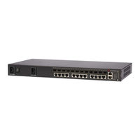
Brocade Communications Systems 6910 Manuals
Manuals and User Guides for Brocade Communications Systems 6910. We have
3
Brocade Communications Systems 6910 manuals available for free PDF download: Installation Manual, Manual, Hardware Installation Manual
Brocade Communications Systems 6910 Installation Manual (82 pages)
Ethernet Access Switch
Brand:
Brocade Communications Systems
| Category:
Switch
| Size: 2 MB
Table of Contents
Hardware Installation Guide
1
Table of Contents
3
About this Document
11
Audience
11
Supported Hardware and Software
11
Document Conventions
11
Text Formatting
11
Notes, Cautions, and Danger Notices
12
Related Publications
12
Getting Technical Help or Reporting Errors
13
Chapter 1 Introduction
15
Overview
15
Figure 1 Gbe ACCESS RINGS
15
Figure 2 FRONT PANEL Brocade 6910 Switch
16
Figure 3 FRONT PANEL Brocade 6910 Switch
16
Switch Architecture
17
Network Management Options
17
Description of Hardware
18
SFP Slots
18
10/100/1000BASE-T Ports
19
10/100/1000BASE-T Management Port (the Craft Interface)
19
Console Port
19
Alarm Interface Port
19
Port and System Status Leds
19
Figure 6 PORT and SYSTEM Leds
20
Power Supply Sockets
21
Figure 7 Brocade 6910 Switch - AC Power Supply Sockets
21
Figure 8 Brocade 6910 Switch-DC Power Supply Sockets
21
Chapter 2 Installing the Switch
23
Selecting a Site
23
Ethernet Cabling
24
Equipment Checklist
24
Package Contents
24
Figure 9 RJ-45 CONNECTIONS
24
Mounting
25
Desktop or Shelf Mounting
25
Rack Mounting
25
Figure 10 ATTACHING the ADHESIVE FEET
25
Figure 11 ATTACHING the BRACKETS
26
Figure 12 INSTALLING the SWITCH in a RACK
26
Installing an Optional SFP Transceiver
27
Grounding the Chassis
27
Figure 13 INSTALLING an OPTIONAL SFP TRANSCEIVER
27
Connecting to a Power Source
28
Figure 14 GROUNDING POINT
28
Connecting DC Power
29
Figure 15 DC PLUG CONNECTIONS
30
Figure 16 DC PLUG CONNECTIONS 2
31
Connecting AC Power
32
Connecting to the Console Port
32
Figure 17 AC POWER SOCKETS
32
Figure 18 CONSOLE CABLE
33
Wiring Map for Serial Cable
33
Connecting to the Alarm Port
34
Wiring Map for Alarm Cable
34
Figure 4 Figure
34
Figure 19 ALARM PORT (D-15) PIN out
34
Figure 20 EXTERNAL ALARM I/O CONNNECTORS
35
Chapter 3 Making Network Connections
37
Connecting Network Devices
37
Twisted-Pair Devices
37
Cabling Guidelines
37
Connecting to Pcs, Servers, Hubs and Switches
37
Fiber Optic Devices
38
Figure 21 MAKING CONNECTIONS to SFP TRANSCEIVERS
38
Troubleshooting
39
Appendix A Troubleshooting
39
Diagnosing Switch Indicators
39
In-Band Access
39
Cables
41
Appendix B Cables
41
Twisted-Pair Cable and Pin Assignments
41
10BASE-T/100BASE-TX Pin Assignments
41
Figure 22 RJ-45 CONNECTOR PIN NUMBERS
41
Straight-Through Wiring
42
Crossover Wiring
42
Figure 23 STRAIGHT-THROUGH WIRING
42
1000BASE-T Pin Assignments
43
Cable Testing for Existing Category 5 Cable
43
Figure 24 CROSSOVER WIRING
43
Adjusting Existing Category 5 Cabling to Run 1000BASE-T
44
Fiber Standards
44
Specifications
45
Appendix C Specifications
45
Physical Characteristics
45
Ports
45
Network Interface
45
Buffer Architecture
45
Aggregate Bandwidth
45
Switching Database
45
Leds
45
Weight
45
Size
46
Temperature
46
Humidity
46
AC Input
46
DC Input
46
Power Supply
46
Power Consumption
46
Maximum Current
46
Switch Features
46
Forwarding Mode
46
Throughput
47
Flow Control
47
Management Features
47
In-Band Management
47
Out-Of-Band Management
47
Software Loading
47
Standards
47
Compliances
47
Emissions
47
Immunity
48
Safety
48
Appendix D Caution and Danger Notices
49
English / French
49
Cautions
49
Dangers
51
Appendix E Caution and Danger Notices
55
German / Spanish / Chinese
55
Cautions
55
Dangers
58
Spanish (Only)
60
Chinese (Traditional)
66
Taiwan BSMI Statement
74
Chinese (Simplified)
75
Glossary
77
Advertisement
Brocade Communications Systems 6910 Manual (80 pages)
Ethernet Access Switch
Brand:
Brocade Communications Systems
| Category:
Switch
| Size: 0 MB
Table of Contents
Table of Contents
5
About this Document
9
In this Chapter
9
Supported Hardware and Software
9
Document Conventions
10
Text Formatting
10
Notes
10
Related Publications
10
Getting Technical Help
11
Document Feedback
11
Chapter 1 Overview of the Brocade 6910 MIB
13
Introduction
13
Obtaining and Installing the Brocade 6910 Mibs
13
Downloading the MIB from Technical Support Web Site
13
Downloading the MIB from Brocade FTP Site
13
Importing the Brocade MIB into a UNIX Environment
13
Reloading Mibs into a Third-Party NMS
14
Standard Objects
14
Proprietary Objects
14
Structure of this Guide
16
Snmpv3 Support
16
Chapter 2 Supported Standard Mibs
17
Supported on Brocade 6910 Switches
17
RFC Compliance - Management
17
IEEE Standards
18
LLDP MIB Support
18
Partially Supported Standards
18
RFC 1213: Management Information Base (MIB-II)
19
RFC 1493: Definitions of Managed Objects for Bridges
19
RFC 1611: DNS Server MIB Extensions
19
RFC 1612: DNS Resolver MIB Extensions
20
RFC 2021: Remote Network Monitoring Management
21
Information Base, Version 2
21
RFC 2096: IP Forwarding Table MIB
22
RFC 2576: SNMP Community MIB
22
RFC 2674: Definitions of Managed Objects for Bridges with Traffic Classes, Multicast Filtering and Virtual LAN Extensions
22
RFC 2737: Entity MIB, Version 2
23
RFC 2819: Remote Network Monitoring Management
23
Information Base
23
RFC 2863: Interfaces Group MIB
24
RFC 2925: Ping MIB
24
RFC 2925: Remote Trace MIB
25
RFC 3413: SNMP Notification MIB
26
RFC 3635: Ethernet-Like Interface Types
26
RFC 3636: IEEE 802.3 Medium Attachment Units (MAU) MIB
26
IEEE 802.1Ag: Connectivity Fault Management (CFM) MIB
27
RFC 4878: OAM Functions on Ethernet-Like Interfaces MIB
28
Chapter 3 Registration
31
Chapter 4 Physical Properties of a Device
33
Common Objects
33
Power Supply
33
Boards
33
Chassis Table
33
General Chassis
34
Power Supply Table
34
Temperature
34
Chapter 5 Basic Configuration and Management
35
Software Image
35
Reload
35
File Download and Upload
36
Software Image Details
38
Software Configuration
40
Switch IP Configurations
40
SNTP Server Table
40
Media Table
41
Chapter 6 User Access
43
Agent User Access Group
43
General Security Objects
43
Authorization and Accounting
44
RADIUS General Group
44
RADIUS Server Table
45
TACACS General Objects
46
TACACS Server Table
47
Chapter 7 Multi-Device Port Authentication
49
Multi-Device Port Authentication
49
Global Multi-Device Port Authentication Objects
49
Clear Interface Multi-Device Port Authentication Objects
49
Multi-Device Port Authentication Objects
50
Multi-Device Port Authentication Clear Sessions
50
Chapter 8 Traffic Security
53
Dynamic ARP Inspection VLAN Configuration Table
53
DAI VLAN Configuration Table
53
Dynamic ARP Inspection Interface Configuration Table
54
Dynamic Host Configuration Protocol
54
DHCP Snooping Global Scalar Object
55
DHCP Snooping VLAN Configuration Table
55
DHCP Snooping Interface Configuration Table
55
IP Source Guard
56
IP Source Guard Interface Configuration Table
56
Chapter 9 MAC-Based VLAN
57
MAC-Based VLAN Global Objects
57
Chapter 10 Interfaces
59
Switch Port Information
59
Switch Port Information Group
59
Link Aggregation Group (LAG) Table
61
Fdrylinkaggregationgrouptable
61
Chapter 11 Monitoring and Logging
63
CPU Utilization
63
System DRAM Information Group
63
Global ARP Statistics
64
Support for Optical Monitoring
64
System Logging
65
System Log Server Table
65
Chapter 12 Object for Stacking
67
Agent Temperature Table for Stacking
67
Chapter 13 Traps and Objects to Enable Traps
69
Objects for Brocade 6910 Switch Traps
69
Trap Information
69
Trap Receiver Table
69
Standard Traps
70
System Status Traps
70
Traps for Spanning Tree Protocol
71
Traps for RMON Events
71
Ironware Traps
72
General Traps
72
Port Security Traps
73
Traps for Stacking
73
Examples
74
RMON Event Traps
74
Brocade Communications Systems 6910 Hardware Installation Manual (78 pages)
Brand:
Brocade Communications Systems
| Category:
Network Router
| Size: 3 MB
Table of Contents
Document History
2
Table of Contents
3
About this Document
11
In this Chapter
11
Audience
11
Supported Hardware and Software
11
Document Conventions
11
Text Formatting
11
Notes, Cautions, and Danger Notices
12
Related Publications
12
Getting Technical Help or Reporting Errors
13
Chapter 1 Introduction
15
Figure 1 Gbe ACCESS RINGS
15
Figure 2 FRONT PANEL Brocade 6910 Switch
16
Figure 3 FRONT PANEL Brocade 6910 Switch
16
Network Management Options
17
Rear Panel
17
Side Panel
17
Switch Architecture
17
Description of Hardware
18
SFP Slots
18
10/100/1000BASE-T Ports
19
10/100/1000BASE-T Management Port (the Craft Interface)
19
Console Port
19
Alarm Interface Port
19
Port and System Status Leds
19
Figure 6 PORT and SYSTEM Leds
20
Power Supply Sockets
21
Figure 7 Brocade 6910 Switch - AC Power Supply Sockets
21
Figure 8 Brocade 6910 Switch-DC Power Supply Sockets
21
Chapter 2 Installing the Switch
23
Selecting a Site
23
Ethernet Cabling
23
Equipment Checklist
24
Package Contents
24
Figure 9 RJ-45 CONNECTIONS
24
Mounting
25
Desktop or Shelf Mounting
25
Rack Mounting
25
Figure 10 ATTACHING the ADHESIVE FEET
25
Figure 11 ATTACHING the BRACKETS
26
Figure 12 INSTALLING the SWITCH in a RACK
26
Installing an Optional SFP Transceiver
27
Grounding the Chassis
27
Figure 13 INSTALLING an OPTIONAL SFP TRANSCEIVER
27
Connecting to a Power Source
28
Figure 14 GROUNDING POINT
28
Connecting DC Power
29
Figure 15 DC PLUG CONNECTIONS
30
Figure 16 DC PLUG CONNECTIONS 2
31
Connecting AC Power
32
Connecting to the Console Port
32
Figure 17 AC POWER SOCKETS
32
Figure 18 CONSOLE CABLE
33
Wiring Map for Serial Cable
33
Connecting to the Alarm Port
34
Wiring Map for Alarm Cable
34
Figure 19 ALARM PORT (D-15) PIN out
34
Figure 20 EXTERNAL ALARM I/O CONNNECTORS
35
Chapter 3 Making Network Connections
37
Connecting Network Devices
37
Twisted-Pair Devices
37
Cabling Guidelines
37
Connecting to Pcs, Servers, Hubs and Switches
37
Fiber Optic Devices
37
Figure 21 MAKING CONNECTIONS to SFP TRANSCEIVERS
38
Troubleshooting
41
Appendix A Troubleshooting
41
Diagnosing Switch Indicators
41
In-Band Access
41
Appendix B Cables
43
Twisted-Pair Cable and Pin Assignments
43
10BASE-T/100BASE-TX Pin Assignments
43
Figure 22 RJ-45 CONNECTOR PIN NUMBERS
43
Straight-Through Wiring
44
Crossover Wiring
44
Figure 23 STRAIGHT-THROUGH WIRING
44
1000BASE-T Pin Assignments
45
Cable Testing for Existing Category 5 Cable
45
Figure 24 CROSSOVER WIRING
45
Adjusting Existing Category 5 Cabling to Run 1000BASE-T
46
Fiber Standards
46
Specifications
47
Appendix C Specifications
47
Physical Characteristics
47
Ports
47
Network Interface
47
Buffer Architecture
47
Aggregate Bandwidth
47
Switching Database
47
Leds
47
Weight
47
Size
48
Temperature
48
Humidity
48
AC Input
48
DC Input
48
Power Supply
48
Power Consumption
48
Maximum Current
48
Switch Features
48
Forwarding Mode
48
Throughput
49
Flow Control
49
Management Features
49
In-Band Management
49
Out-Of-Band Management
49
Software Loading
49
Standards
49
Compliances
49
Emissions
49
Immunity
50
Safety
50
Caution and Danger Notices
51
Appendix D Caution and Danger Notices
51
Cautions
51
Dangers
54
Spanish
58
Chinese (Traditional)
63
Glossary
73
Advertisement
Advertisement
Related Products
Brocade Communications Systems PowerConnect 6510
Brocade Communications Systems ICX 6450-C12-PD
Brocade Communications Systems Brocade 6520
Brocade Communications Systems Mobility 650
Brocade Communications Systems 6505
Brocade Communications Systems FCX 624S-HPOE
Brocade FCX 648S-HPOE
Brocade Communications Systems 6542
Brocade Communications Systems 200E Series
Brocade Communications Systems 300
Brocade Communications Systems Categories
Switch
Software
Network Router
Storage
Server
More Brocade Communications Systems Manuals
Login
Sign In
OR
Sign in with Facebook
Sign in with Google
Upload manual
Upload from disk
Upload from URL