Sign In
Upload
Manuals
Brands
Autronica Manuals
Smoke Alarm
Autroprime
Autronica Autroprime Manuals
Manuals and User Guides for Autronica Autroprime. We have
3
Autronica Autroprime manuals available for free PDF download: Installation Handbook, Operator's Handbook Manual, Connecting
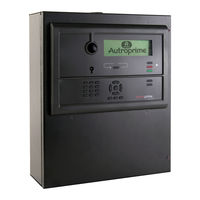
Autronica Autroprime Operator's Handbook Manual (82 pages)
Autroprime Interactive Fire Detection System
Brand:
Autronica
| Category:
Fire Alarms
| Size: 0 MB
Table of Contents
Table of Contents
3
1 Introduction
7
About the Handbook
7
The Reader
7
Reference Documentation
7
Components
8
2 The Operator Panel
9
Introduction
9
Indicators
10
Upper Section
10
Lower Section
11
The Panel Display
12
Operating Buttons
12
Function Buttons
12
More Events Button
14
Alphanumeric Keypad
14
Manoeuvre and Utility Buttons
15
Internal Buzzer
16
3 Operation Mode
17
Loop Topology Presentation
17
The Panel's Idle State
17
Conditions
17
Alarm Levels
18
Access Levels
18
How Events Are Presented in the Display
19
How to View Detailed Information
19
Resounding the Internal Buzzer
20
Resounding Fire Alarm Devices
20
Disablement Sources
20
Overview
20
Point Disablements
21
Alarm Organization
22
Detection Zones with Different Properties
22
The Actioning of Alarm Zones
22
Immediate Action Detection Zones
22
Dependency Action Detection Zones
23
Delayed Action Detection Zones
24
Delayed Dependency Detection Zones
25
SOLAS Detection Zones
26
Silent, Small and Large Alarm - Overview
26
4 About «In the Event of
28
5 In the Event of a Fire Alarm
29
Indications in the Event of a Fire Alarm
29
Actions to be Taken in the Event of a Fire Alarm
29
6 In the Event of a Pre Alarm
34
Indications in the Event of a Pre Alarm
34
Actions to be Taken in the Event of a Pre Alarm
34
7 In the Event of a Fire Alarm - with Alarm Delay
36
Indications - Fire Alarm with Alarm Delay
36
Actions to be Taken - Fire Alarm with Alarm Delay
36
8 In the Event of Faults
39
Indications in the Event of Faults
39
Actions to be Taken in the Event of Faults
39
9 Supervisory
42
Indications During Supervisory
42
Actions to be Taken During Supervisory
42
10 Menu Mode
44
Menu Structure
44
How to Enter Menu Mode
44
How to Enter Service Mode
45
11 System Status
46
Introduction
46
System Status Menu
46
Example - System Status, Alarms
46
12 Disabling
48
Introduction
48
Disable Menu
48
Disabling Activated / Deactivated Components
49
Disabling Detection Zones
49
Disabling Alarm Zones
49
Disabling Points
49
Disabling Fire Alarm Devices
50
Disabling Outputs (Loop Outputs/Local Outputs)
50
Disabling Inputs (Loop Inputs/Local Inputs)
50
Disabling Routing Equipment
50
Example - How to Disable a Detection Zone
51
13 Enabling
53
Introduction
53
Enable Menu
53
Enabling Deactivated Components
54
Enabling Detection Zones
54
Enabling Alarm Zones
54
Enabling Points
54
Enabling Fire Alarm Devices
54
Enabling Outputs (Loop Outputs/Local Outputs)
55
Enabling Inputs (Loop Inputs/Local Inputs)
55
Enabling Routing Equipment
55
How to Execute Commands from the Enable Menu
56
Enable Delays
57
14 Show Unit Properties
58
Introduction
58
Show Unit Properties Menu
58
Detection Zones
59
Alarm Zones
59
Points
60
Fire Alarm Device
60
Loop Outputs
61
Local Outputs
62
Loop Inputs
62
Local Inputs
63
MIMIC Panels
63
Activation Groups
64
External Interfaces
64
Serial Port Settings
64
TCP/IP Port Settings (Ethernet)
65
ESPA Interface Settings
65
MODBUS Interface Settings
66
Voyage Data Recorder (VDR)
66
Detection Loops
67
Operator Panels
67
15 Report
68
Introduction
68
Report Menu
68
Read Log
68
Show Topology
69
Show Date and Time
69
Software Version Information
69
Configuration Version Information
69
16 Service Commands
70
Introduction
70
Service Menu
70
Testing Detection Zones
71
Testing Alarm Zones
72
Testing Fire Alarm Devices
72
Testing Loop Outputs
73
Local Outputs
74
Appendix
75
Reader's Comments
79
Advertisement
Autronica Autroprime Installation Handbook (86 pages)
Interactive Fire Detection System
Brand:
Autronica
| Category:
Fire Alarms
| Size: 2 MB
Table of Contents
Table of Contents
3
1 Introduction
7
About the Handbook
7
The Reader
7
Reference Documentation
7
2 Pre-Installation
8
Location
8
Environmental Requirements
8
Mounting Height / Space Requirement
8
Mounting Alternatives
8
3 Panels, Brackets and Cabinet
9
4 Interconnecting Panels on the Panel Bus
11
Overview
11
5 Mounting Instructions
12
6 Addressing Panels
15
Rotary Switch on Panels
15
Addressing the Fire Alarm Control Panel (BS-200)
15
Addressing Other Panels
15
Addressing MIMIC Drivers
15
7 Mounting Drawings
16
Hole Dimensions - Mounting Bracket for BS-210 and BS-211
16
Hole Dimensions - Mounting Bracket for BU-210, BU-211 and BV-210
17
8 Cable Specifications
18
Calculating the Current Consumption
18
Tables
18
Onboard I/O and Power
19
Panel Bus and Serial Port
20
Detection Loop Cables
20
The Panel Bus Cable Requirements
21
Characteristic Impedance and Signal Attenuation
21
High-Voltage and Noisy Environments
21
Cable Length and Power Consumption
22
Calculation of Power Consumption and Cable Loss
24
Power Supply and Battery Capacity
24
9 Cable Connections
25
Cabling - Overview
25
Overview Internal Cable Layout
27
Battery Connections
28
Connections to Power Supply / Mains Power
30
Fuses
31
Connection of External DC Power
32
Terminal Points Overview - Main Board
33
Description of Terminal Points - Main Board
34
Main Terminal Block J1
34
Ethernet RJ45 Connector J2
37
Power Supply Control and Battery Temperature Measurement J3
37
Auxiliary Term Inal Block J4
38
Add-On Network Interface, J5
38
Auxiliary Terminal Block J6
39
Operator Panel, Standalone, J7
39
Add-On Looper Interface J8
40
USB Host J10
40
User Configurable Inputs
40
User Configurable Outputs
41
Cable Connections Inside the Cabinet (Fire Alarm Control Panel)
42
Connections (J7) for a Standalone Cabinet with Integrated BS-210
42
Connections (J4) for a Cabinet with External BS-210 and no External Panel Bus
43
Connections (J4) for a Cabinet with Integrated BS-210 and External Panel Bus
44
Connections (J4) for a Cabinet with External BS-210 and External Panel Bus
45
Panel Bus Connections to BU-, BV- and BS-Panels
46
Overview Panel Bus
47
Connections to MIMIC Drivers (BUR-200)
48
Terminal Points - Overview
49
Switch Settings
50
Connection of Master and Slave MIMIC Drivers
50
Connections for Panel Bus
51
Connections for Slave Panels
51
Terminals for Monitored Inputs
51
Ground Fault
52
10 Maritime Installations
53
Typical Maritime Installation - Overview
53
Fire Alarm Control Panel BS-200M
54
External Connections
54
Detection Loop Connections - Extended Terminal Block
55
Internal Wiring
56
Panel Bus Connection
59
MIMIC Cabinet BUR-200
60
External Battery Cabinet
61
Dimensions
61
Internal Connections in Battery Cabinet
63
11 Startup
64
Power up
64
12 Switches and Indicators on the Main Board
66
Overview
66
Reset Switch (S1)
66
Dip-Switches for Mode Settings (S2)
67
Battery Short-Circuit Protection
67
Battery Restart after Deep Discharge (S3)
68
Serial Port Settings (S4)
69
System Fault LED Indicator (Yellow)
69
Status LED Indicator (Red)
69
Power LED Indicator (Green)
69
Regulated 24V Indicator (Green)
69
13 Exporting / Importing Configuration Data
70
USB Output
70
Entering the Service Menu
71
Exporting Configuration Data
73
Importing Configuration Data
73
Backup Current Configuration
74
Select Configuration & Restart System
74
Save Configuration
75
14 Changes on the Detection Loop
76
Typical Scenarios
76
Remove a Unit and Insert the same Unit
76
Remove a Unit and Insert Another Unit of the same Type
77
Remove a Unit and Insert Another Unit of a Different Type
77
Add a New Unit to the Detection Loop
78
Remove a Loop Unit from the Detection Loop
78
Major Changes / Clear Loop Config. - Restart System
79
15 Changes on the Panel Bus
80
Typical Scenarios
80
Adding an Extra Panel to the Panel Bus
80
Removing a Panel from the Panel Bus
81
Replacing a Panel of the same Type and with the same Address
81
Replacing a Panel of the same Type but with a Different Address
82
Replacing a Panel of a Different Type
82
16 Appendix
83
Text Foils
83
Autronica Autroprime Connecting (38 pages)
Interactive Fire Detection Systems
Brand:
Autronica
| Category:
Smoke Alarm
| Size: 2 MB
Table of Contents
Table of Contents
3
Autronica Fire and Security as Page
3
1 Introduction
5
About the Handbook
5
The Reader
5
2 Connections to Detectors
6
Connecting Detectors
6
LED Connection on Detector
6
Connection of Branch-Off
7
Detector Head / Base Alignment
8
Detector Label
8
Detector Locking Mechanism
9
Detector Base
9
Detector Head
9
Removing a Locked Detector Head
10
Detector Dust Covers
11
3 Connections to Other Loop Units
12
Introduction
12
Manual Call Points
12
Autrosense Micra 25 High Sensitivity Aspirating Detector
13
Autrosense Micra 100 High Sensitivity Aspirating Detector
14
Autrosense 75 Aspirating Smoke Detector
15
Autrosense 200 High Sensitivity Aspirating Detector
16
Autroflame X33AF Multispectrum Infrared Flame Detector
17
Autrobeam 100 Infrared Beamdetector System
18
Autrobeam 25 Infrared Beamdetector
19
Programmable Electronic Sounders (BBR-200)
20
Addressable Socket Sounder (BBR-110)
21
Ex Ia-Approved Detectors
22
Disable Input with Pushbuttons (BW-200)
23
Door Control Unit (BN-320/2)
24
Monitoring and Control Unit (BN-320/4)
25
Sprinkler Control Unit (BN-320/5)
26
Monitoring Input Unit (BN-201)
27
Input Unit with Selfverify (BN-300)
28
Single Relay Output Unit (BN-310)
29
Day/Night Control Unit with Pushbuttons (BW-202)
30
Disable Input with Timer Input (BW-201)
31
Day/Night Control Unit with Timer Input (BW-203)
32
Remote Alarm Control Unit (BU-200)
33
Interface Unit for Conventional Loops (BN-330)
34
Advertisement
Advertisement
Related Products
Autronica Autro Safe
Autronica AutroSafe Self Verify
Autronica AutroSense Nano
Autronica Autroprime Interactive Fire Detection System
Autronica Autroprime BS-200M
Autronica AutroMaster ISEMS
Autronica AutroSafe BS-310
Autronica AutroSense 75
Autronica AutroVoice miniVES Series
Autronica AutroVoice miniVES 2001
Autronica Categories
Fire Alarms
Security Sensors
Control Panel
Smoke Alarm
Measuring Instruments
More Autronica Manuals
Login
Sign In
OR
Sign in with Facebook
Sign in with Google
Upload manual
Upload from disk
Upload from URL