Sign In
Upload
Manuals
Brands
Automation Direct Manuals
Controller
DL05
Automation Direct DL05 Logic Controller Manuals
Manuals and User Guides for Automation Direct DL05 Logic Controller. We have
3
Automation Direct DL05 Logic Controller manuals available for free PDF download: User Manual, Getting Started
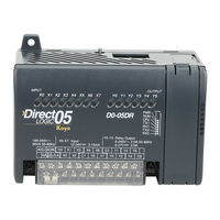
Automation Direct DL05 User Manual (317 pages)
Micro PLC
Brand:
Automation Direct
| Category:
Controller
| Size: 4 MB
Table of Contents
Table of Contents
5
Chapter 6: Drum Instruction Programming
21
DL05 Drum Introduction
21
Purpose
21
Drum Terminology
21
Drum Chart Representation
22
Output Sequences
22
Step Transitions
23
Drum Instruction Types
23
Timer-Only Transitions
23
Timer and Event Transitions
24
Event-Only Transitions
25
Counter Assignments
25
Last Step Completion
26
Overview of Drum Operation
27
Drum Instruction Block Diagram
27
Powerup State of Drum Registers
28
Drum Control Techniques
29
Drum Control Inputs
29
Self-Resetting Drum
30
Initializing Drum Outputs
30
Using Complex Event Step Transitions
30
Drum Instruction
31
Timed Drum with Discrete Outputs (DRUM)
31
Event Drum (EDRUM) Instruction
33
Program Using the Handheld Programmer
35
Chapter 7: RLL PLUS Stage Programming
39
Introduction to Stage Programming
39
Overcoming "Stage Fright
39
Learning to Draw State Transition Diagrams
40
Introduction to Process States
40
The Need for State Diagrams
40
A 2-State Process
40
RLL Equivalent
41
Stage Equivalent
41
Let's Compare
42
Initial Stages
42
What Stage Bits Do
43
Stage Instruction Characteristics
43
Using the Stage Jump Instruction for State Transitions
44
Stage Jump, Set, and Reset Instructions
44
Stage Program Example: Toggle On/Off Lamp Controller
45
A 4-State Process
45
Four Steps to Writing a Stage Program
46
Stage Program Example: a Garage Door Opener
47
Garage Door Opener Example
47
Draw the Block Diagram
47
Draw the State Diagram
48
Add Safety Light Feature
49
Modify the Block Diagram and State Diagram
49
Using a Timer Inside a Stage
50
Add Emergency Stop Feature
51
Exclusive Transitions
51
Stage Program Design Considerations
52
Stage Program Organization
52
How Instructions Work Inside Stages
53
Using a Stage as a Supervisory Process
54
Stage Counter
54
Power Flow Transition Technique
55
Stage View in Directsoft 5
55
Parallel Processing Concepts
56
Parallel Processes
56
Converging Processes
56
Convergence Stages (CV)
56
Convergence Jump (CVJMP)
57
Convergence Stage Guidelines
57
RLL PLUS (Stage) Instructions
58
Stage (SG)
58
Initial Stage (ISG)
59
Jump (Jmp)
59
Not Jump (NJMP)
59
Converge Stage (CV) and Converge Jump (CVJMP)
60
Questions and Answers about Stage Programming
62
Chapter 8: PID Loop Operation
65
DL05 PID Control
65
DL05 PID Control Features
65
Introduction to PID Control
67
What Is PID Control
67
Introducing DL05 PID Control
69
Process Control Definitions
71
PID Loop Operation
72
Position Form of the PID Equation
72
Reset Windup Protection
73
Freeze Bias
74
Adjusting the Bias
74
Step Bias Proportional to Step Change in SP
75
Eliminating Proportional, Integral or Derivative Action
75
Velocity Form of the PID Equation
75
Bumpless Transfer
76
Loop Alarms
76
Loop Operating Modes
77
Special Loop Calculations
77
Ten Steps to Successful Process Control
79
PID Loop Setup
81
Some Things to Do and Know before Starting
81
PID Error Flags
81
Establishing the Loop Table Size and Location
81
Loop Table Word Definitions
83
PID Mode Setting 1 Bit Descriptions (Addr + 00)
84
PID Mode Setting 2 Bit Descriptions (Addr + 01)
85
Mode/Alarm Monitoring Word (Addr + 06)
86
Ramp/Soak Table Flags (Addr + 33)
86
Ramp/Soak Table Location (Addr + 34)
87
Ramp/Soak Table Programming Error Flags (Addr + 35)
87
Configure the PID Loop
88
PID Loop Tuning
103
Open-Loop Test
103
Manual Tuning Procedure
104
Auto Tuning Procedure
107
Use Directsoft 5 Data View with PID View
111
Open a New Data View Window
111
Open PID View
112
How to Change Loop Modes
114
Operator Panel Control of PID Modes
115
PLC Modes Effect on Loop Modes
115
Loop Mode Override
115
PV Analog Filter
116
Creating an Analog Filter in Ladder Logic
117
Use the Directsoft 5 Filter Intelligent Box Instruction
118
Filterb Example
118
Ramp/Soak Generator
119
Introduction
119
Ramp/Soak Table
120
Ramp/Soak Table Flags
122
Ramp/Soak Generator Enable
122
Ramp/Soak Controls
122
Ramp/Soak Profile Monitoring
123
Ramp/Soak Programming Errors
123
Testing Your Ramp/Soak Profile
123
Directsoft 5 Ramp/Soak Example
124
Setup the Profile in PID Setup
124
Program the Ramp/Soak Control in Relay Ladder
124
Test the Profile
125
Cascade Control
126
Introduction
126
Cascaded Loops in the DL05 CPU
127
Tuning Cascaded Loops
128
Time-Proportioning Control
129
On/Off Control Program Example
130
Feedforward Control
131
Feedforward Example
132
PID Example Program
133
Program Setup for the PID Loop
133
Troubleshooting Tips
135
Glossary of PID Loop Terminology
137
Bibliography
139
Chapter 9: Maintenance and Troubleshooting
141
Hardware System Maintenance
141
Standard Maintenance
141
Diagnostics
141
Fatal Errors
141
Non-Fatal Errors
141
V-Memory Error Code Locations
142
Special Relays (SP) Corresponding to Error Codes
142
DL05 Micro PLC Error Codes
143
Program Error Codes
144
CPU Indicators
145
RUN Indicator
146
CPU Indicator
146
Communications Problems
146
I/O Point Troubleshooting
147
Possible Causes
147
Some Quick Steps
147
Handheld Programmer Keystrokes Used to Test an Output Point
148
Noise Troubleshooting
149
Electrical Noise Problems
149
Reducing Electrical Noise
149
Machine Startup and Program Troubleshooting
150
Syntax Check
150
Special Instructions
151
Duplicate Reference Check
152
Runtime Edits
154
Forcing I/O Points
155
Bit Forcing with Direct Access
155
Chapter 10 : Memory Cartridge/Real Time Clock
157
General Information about the D0-01MC
157
Jumper Selects Write Enable or Disable
157
Low Battery Alert
157
Clock/Calendar
157
Specifications
157
New Ladder Instructions
157
Error Code Changes
157
Setting the Write Enable/Disable Jumper
158
Write Enable
158
Write Disable
158
Plugging-In the Memory Cartridge
159
Remove the Slot Cover
159
Insert the Memory Cartridge
159
Software and Firmware Requirements
160
How to Update Your Directsoft Programming Software
160
How to Update Your DL05 Firmware
160
Naming the Memory Cartridge
161
Up to 8 Alphanumeric Characters
161
Name Is Retained in Cartridge Memory and Project Folder
161
Setting the Time and Date
162
Memory Transfers
163
CPU to MC
163
MC to CPU
163
LED Indicator Lights
164
Password Protected Programs
164
Memory Map and Forwarding Range
165
Battery Back-Up During AC Power Loss
166
What if the Battery dies
166
Battery Type
166
Removing and Replacing the Battery
166
Specifications and Agency Approvals
167
Clock/Calendar Instructions
168
Date (DATE)
168
Time (TIME)
169
Move Memory Cartridge / Load Label (MOVMC) (LDLBL)
170
Copy Data from a Data Label Area to V-Memory
171
Copy Data from V-Memory to a Data Label Area
172
Error Codes
173
Appendix A: Auxiliary Functions
175
Introduction
175
Purpose of Auxiliary Functions
175
Accessing AUX Functions Via Directsoft 5
176
Accessing AUX Functions Via the Handheld Programmer
176
Aux 2* Rll Operations
176
AUX 21 Check Program
177
AUX 22 Change Reference
177
AUX 23 Clear Ladder Range
177
AUX 24 Clear Ladders
177
AUX 3* - V-Memory Operations
177
AUX 31 Clear V-Memory
177
AUX 2* - RLL Operations
177
AUX 4* - I/O Configuration
178
AUX 41 Show I/O Configuration
178
AUX 5* - CPU Configuration
178
AUX 51 Modify Program Name
178
AUX 53 Display Scan Time
178
AUX 54 Initialize Scratchpad
178
AUX 55 Set Watchdog Timer
178
AUX 56 CPU Network Address
179
AUX 57 Set Retentive Ranges
179
AUX 58 Test Operations
179
AUX 59 Bit Override
180
AUX 5B Counter Interface Configuration
180
AUX 5D Select PLC Scan Mode
180
AUX 6* - Handheld Programmer Configuration
181
AUX 61 Show Revision Numbers
181
AUX 62 Beeper On/Off
181
AUX 65 Run Self Diagnostics
181
AUX 7* - EEPROM Operations
181
Transferrable Memory Areas
181
AUX 71 CPU to HPP EEPROM
181
AUX 72 HPP EEPROM to CPU
182
AUX 73 Compare HPP EEPROM to CPU
182
AUX 74 HPP EEPROM Blank Check
182
AUX 75 Erase HPP EEPROM
182
AUX 76 Show EEPROM Type
182
AUX 8* - Password Operations
182
AUX 81 Modify Password
182
AUX 82 Unlock CPU
183
AUX 83 Lock CPU
183
Appendix B: DL05 Error Codes
184
DL05 Error Codes
184
Appendix C: Instruction Execution Times
193
Introduction
193
V-Memory Data Registers
193
V-Memory Bit Registers
193
How to Read the Tables
193
Instruction Execution Times
194
Boolean Instructions
194
Comparative Boolean Instructions
195
Immediate Instructions
201
Timer, Counter and Shift Register
201
Accumulator Data Instructions
202
Logical Instructions
203
Math Instructions
203
Bit Instructions
205
Number Conversion Instructions
205
CPU Control Instructions
206
Program Control Instructions
206
Interrupt Instructions
206
Network Instructions
206
Message Instructions
207
RLL PLUS Instructions
207
Drum Instructions
207
Word Bit Instructions
208
Appendix D: Special Relays
210
DL05 PLC Special Relays
210
Appendix E: High-Speed Input and Pulse Output Features
215
Introduction
215
Built-In Motion Control Solution
215
Availability of HSIO Features
215
Dedicated High-Speed I/O Circuit
216
Wiring Diagrams for each HSIO Mode
216
Choosing the HSIO Operating Mode
217
Understanding the Six Modes
217
Default Mode
217
Configuring the HSIO Mode
218
Mode 10: High-Speed Counter
219
Purpose
219
Functional Block Diagram
219
Wiring Diagram
220
Interfacing to Counter Inputs
220
Interfacing to Counter Outputs
220
Setup for Mode 10
221
Presets and Special Relays
221
Preset Data Starting Location
222
Calculating Your Preset Values
223
Input Configuration
223
Writing Your Control Program
224
Program Example: Counter Without Preset
225
Counter with Presets Program Example
227
Counter with Preload Program Example
229
Troubleshooting Guide for Mode 10
230
Symptom: the Counter Does Not Count
230
Symptom: the Counter Counts but the Presets Do Not Function
230
Symptom: the Counter Counts up but will Not Reset
230
Mode 20: Quadrature Counter
231
Purpose
231
Functional Block Diagram
231
Quadrature Encoder Signals
231
Wiring Diagram
232
Interfacing to Encoder Outputs
232
Setup for Mode 20
233
Input Configuration
233
Writing Your Control Program
234
Quadrature Counter W/Preload Program Example
234
Counter Preload Program Example
236
Troubleshooting Guide for HSIO Mode 20
236
Symptom: the Counter Does Not Count
236
Symptom: the Counter Counts in the Wrong Direction
236
Symptom: the Counter Counts up and down but will Not Reset
236
Mode 30: Pulse Output
237
Purpose
237
Functional Block Diagram
238
Wiring Diagram
239
Interfacing to Drive Inputs
239
Motion Control Profile Specifications
240
Physical I/O Configuration
240
Logical I/O Functions
240
Setup for Mode 30
241
Profile / Velocity Select Register
241
Profile Parameter Table
242
Trapezoidal Profile
242
Registration Profile
242
Velocity Profile
242
Choosing the Profile Type
243
Trapezoidal Profile Defined
243
Registration and Home Search Profiles Defined
243
Velocity Profile Defined
243
Trapezoidal Profile Operation
244
Trapezoidal Profile Applications
244
Trapezoidal Profile Program Example
245
Preload Position Value
246
Registration Profile Operation
247
Registration Applications
247
Registration Profile Program Example
248
Home Search Program Example
250
Velocity Profile Operation
252
Velocity Profile Applications
252
Velocity Profile Program Example
253
Pulse Output Error Codes
255
Troubleshooting Guide for HSIO Mode 30
255
Symptom: the Stepper Motor Does Not Rotate
255
Symptom: the Motor Turns in the Wrong Direction
256
Mode 40: High-Speed Interrupts
257
Purpose
257
Functional Block Diagram
257
Setup for Mode 40
258
Interrupts and the Ladder Program
258
External Interrupt Timing Parameters
259
Timed Interrupt Parameters
259
Input/Timed INT Configuration
259
Independent Timed Interrupt
259
External Interrupt Program Example
260
Timed Interrupt Program Example
261
Mode 50: Pulse Catch Input
262
Purpose
262
Functional Block Diagram
262
Pulse Catch Timing Parameters
262
Setup for Mode 50
263
Input Configuration
263
Pulse Catch Program Example
264
Mode 60: Discrete Inputs with Filter
265
Purpose
265
Functional Block Diagram
265
Input Filter Timing Parameters
265
Setup for Mode 60
266
Input Configuration
266
Filtered Inputs Program Example
267
Appendix F: PLC Memory
269
DL05 PLC Memory
269
Non-Volatile V-Memory in the DL05
270
Appendix G: ASCII Table
272
ASCII Table
272
Appendix H: Product Weights
274
Product Weight Table
274
Appendix I: Numbering Systems
277
Introduction
277
Binary Numbering System
277
Hexadecimal Numbering System
278
Octal Numbering System
279
Binary Coded Decimal (BCD) Numbering System
280
Real (Floating Point) Numbering System
280
Bcd/Binary/Decimal/Hex/Octal -What Is the Difference
281
Data Type Mismatch
282
Signed Vs. Unsigned Integers
283
Automationdirect.com Products and Data Types
284
Directlogic Plcs
284
C-More/C-More Micro-Graphic Panels
284
Appendix J: European Union Directives (CE)
286
European Union (EU) Directives
286
Member Countries
287
Applicable Directives
287
Compliance
287
General Safety
288
Special Installation Manual
289
Other Sources of Information
289
Basic EMC Installation Guidelines
290
Enclosures
290
AC Mains Filters
290
Suppression and Fusing
290
Internal Enclosure Grounding
291
Equi-Potential Grounding
291
Communications and Shielded Cables
291
Analog and RS232 Cables
292
Multidrop Cables
292
Shielded Cables Within Enclosures
293
Analog Modules and RF Interference
293
Network Isolation
293
DC Powered Versions
294
Items Specific to the DL05
294
Appendix K: Introduction to Serial Communications
297
Introduction to Serial Communications
297
Wiring Standards
297
Communications Protocols
299
DL05 Port Specifications
300
DL05 Port Pinouts
300
Port Setup Using Directsoft 5 or Ladder Logic Instructions
301
Port 2 Setup for RLL Using K-Sequence, Directnet or Modbus RTU
302
Port 2 Setup for RLL Using ASCII
303
K-Sequence Communications
305
Directnet Communications
305
Step 1: Identify Master Port # and Slave
305
Step 2: Load Number of Bytes to Transfer
305
Step 3: Specify Master Memory Area
306
Step 4: Specify Slave Memory Area
307
Communications from a Ladder Program
308
Multiple Read and Write Interlocks
308
Modbus RTU Communications
309
Index
310
Advertisement
Automation Direct DL05 Getting Started (13 pages)
Brand:
Automation Direct
| Category:
Controller
| Size: 0 MB
Table of Contents
Table of Contents
1
Introduction
2
Conventions Used
3
DL05 Micro PLC Components
4
Quick Start for PLC Checkout and Programming
6
Steps to Designing a Successful System
10
Questions and Answers about DL05 Micro Plcs
12
Automation Direct DL05 Getting Started (7 pages)
Brand:
Automation Direct
| Category:
Controller
| Size: 0 MB
Table of Contents
Table of Contents
1
Introduction
2
Conventions Used
2
Module Choices
3
Selecting the Proper Module
3
Analog Modules
4
Specialty Modules
4
Installing the Option Modules
5
Module LED Indicator
6
Power Budgeting
6
Advertisement
Advertisement
Related Products
Automation Direct D0-05AR
Automation Direct D0-05DR
Automation Direct D0-05AD
Automation Direct D0-05DD
Automation Direct D0-05AA
Automation Direct D0-05DA
Automation Direct D0-05DR-D
Automation Direct D0-05DD-D
Automation Direct DL405
Automation Direct DL205 Series
Automation Direct Categories
Controller
Measuring Instruments
I/O Systems
Control Unit
DC Drives
More Automation Direct Manuals
Login
Sign In
OR
Sign in with Facebook
Sign in with Google
Upload manual
Upload from disk
Upload from URL