Sign In
Upload
Manuals
Brands
Ametek Manuals
Measuring Instruments
DDMC
Ametek DDMC Manuals
Manuals and User Guides for Ametek DDMC. We have
1
Ametek DDMC manual available for free PDF download: Instruction Manual
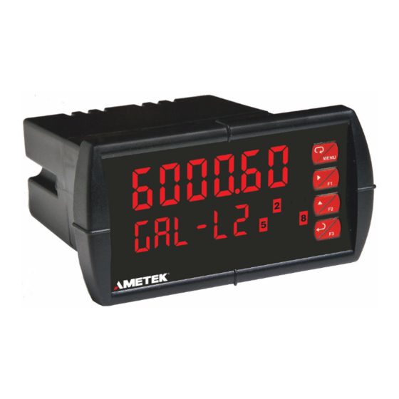
Ametek DDMC Instruction Manual (48 pages)
Analog Input Process Meter / Controller
Brand:
Ametek
| Category:
Measuring Instruments
| Size: 3.07 MB
Table of Contents
Table of Contents
3
Introduction
6
Ordering Information
7
Specifications
8
General
8
Process Input
9
Relays
9
Isolated 4-20 Ma Transmitter Output
10
USB Connection
10
On-Board Digital Input (F4)
10
Modbus ® RTU Serial Communications
10
DDMC Meter View Software
10
Compliance Information
11
Safety
11
Electromagnetic Compatibility
11
Safety Information
11
Installation
11
Unpacking
11
Panel Mounting Instructions
12
Mounting Dimensions
12
Figure 1. 1/8 DIN Panel Cutout Dimensions
12
Figure 2. Panel Mounting Details
12
Figure 3. Meter Dimensions - Side View
12
Figure 4. Meter Dimensions - Top View
12
Enclosure Dimensions
13
Installation Overview
14
DDMC Meter View Software
14
DDMC Meter View Installation
14
Transmitter Supply Voltage Selection (P+, P-)
15
Connections
15
Connectors Labeling
15
Figure 5. Transmitter Supply Voltage Selection
15
Figure 6. PD6000-##0-DB Connectors Label
15
Figure 7. PD6000-##2-DB Connectors Label
15
Figure 8. PD6000-##3-DB Connectors Label
15
Figure 9. PD6000-##4-DB Connectors Label
15
Figure 10. PD6000-##5-DB Connectors Label
15
Figure 11. PD6000-##7-DB Connectors Label
15
Power Connections
16
Signal Connections
16
Modbus RTU Serial Communications
16
Relay Connections
16
Figure 12. Power Connections
16
Figure 13. Transmitters Powered by Internal Supply
16
Figure 14. Transmitter Powered by External Supply or Self-Powered
16
Figure 15. Voltage Input Connections
16
Figure 16. Relay Connections
16
Switching Inductive Loads
17
F4 Digital Input Connections
17
4-20 Ma Output Connections
17
Analog Output Power Supply
17
Figure 17. AC and DC Loads Protection
17
Figure 18. Low Voltage DC Loads Protection
17
Figure 19. F4 Digital Input Connections
17
Figure 20. 4-20 Ma Output Connections
17
Figure 21. Analog Output Supply Powering Other Devices
17
External Relays Connections
18
Interlock Relay Feature
18
Figure 22. Expansion Module & DIN Rail Mounting Kit
18
Figure 23. External Relays Module Connections
18
Figure 24. Interlock Connections
18
Setup and Programming
19
Overview
19
Front Panel Buttons and Status LED Indicators
19
Display Functions & Messages
20
Main Menu
21
Setting Numeric Values
22
Setting up the Meter (Setup)
22
Setting the Input Signal (Input)
22
Setting the Display Units or Custom Tags (Units)
23
Setting the Decimal Point (Dec Pt)
23
Programming the Meter (Prog)
24
Setting the Display Parameter & Intensity (Dsplay)
26
Display Intensity (D-Inty)
26
Setting the Relay Operation (Relay)
27
Setting the Relay Action
27
Programming Set and Reset Points
28
Setting Fail-Safe Operation
28
Programming Time Delay
28
Relay Action for Loss of 4-20 Ma Input (Loop Break)
28
Relay and Alarm Operation Diagrams
28
High Alarm Operation (Set > Reset)
28
Low Alarm Operation (Set < Reset)
29
High Alarm with Fail-Safe Operation (Set > Reset)
29
Low Alarm with Fail-Safe Operation (Set < Reset)
29
Time Delay Operation
29
Pump Alternation Control Operation
30
Relay Sampling Operation
30
Relay Operation Details
31
Overview
31
Relays Auto Initialization
31
Fail-Safe Operation
31
Front Panel Leds
31
Latching and Non-Latching Relay Operation
31
Non-Latching Relay (Auto)
32
Non-Latching Relay with Manual Reset (A-Nman)
32
Latching Relay (Latch)
32
Latching Relay with Clear (Lt-Clr)
32
Acknowledging Relays
33
Pump Alternation Control Applications (Altern)
33
Setting up the Interlock Relay (Force On) Feature
34
Scaling the 4-20 Ma Analog Output (Aout)
35
Reset Menu (Reset)
35
Manual Control Menu (Contrl)
35
Setting up the Password (Pass)
36
Protecting or Locking the Meter
36
Making Changes to a Password Protected Meter
36
Disabling Password Protection
36
Advanced Features Menu
37
Advanced Features Menu & Display Messages
37
Noise Filter (Filter)
38
Noise Filter Bypass (Bypass)
38
Rounding Feature (Round)
38
Modbus RTU Serial Communications (Serial)
38
Select Menu (Select)
39
Input Signal Conditioning (Functn)
39
Low-Flow Cutoff (Cutoff)
40
Analog Output Programming (Aoutpr)
40
Programmable Function Keys User Menu (User)
41
Tare (Tare)
41
Internal Source Calibration (ICAL)
42
Meter Operation
43
Front Panel Buttons Operation
43
Function Keys Operation
43
F4 Operation
43
Maximum/Minimum Readings
43
Troubleshooting
44
Diagnostics Menu (Diag)
44
Determining Software Version
44
Reset Meter to Factory Defaults
44
Factory Defaults & User Settings
45
Troubleshooting Tips
46
EU Declaration of Conformity
47
Advertisement
Advertisement
Related Products
Ametek Drexelbrook Universal IV CM
Ametek JOFRA DTI050 A
Ametek JOFRA DTI050 B
Ametek Dycor Dymaxion Mass Spectrometer
Ametek Dycor DM100M
Ametek Dycor 100 AMU Multiplier
Ametek Dycor 200 AMU
Ametek Dycor DM200M
Ametek Dycor 300 AMU
Ametek DMS-3K
Ametek Categories
Measuring Instruments
Test Equipment
Power Supply
Controller
Laboratory Equipment
More Ametek Manuals
Login
Sign In
OR
Sign in with Facebook
Sign in with Google
Upload manual
Upload from disk
Upload from URL