Sign In
Upload
Manuals
Brands
Allen-Bradley Manuals
Controller
PowerFlex 750 Series
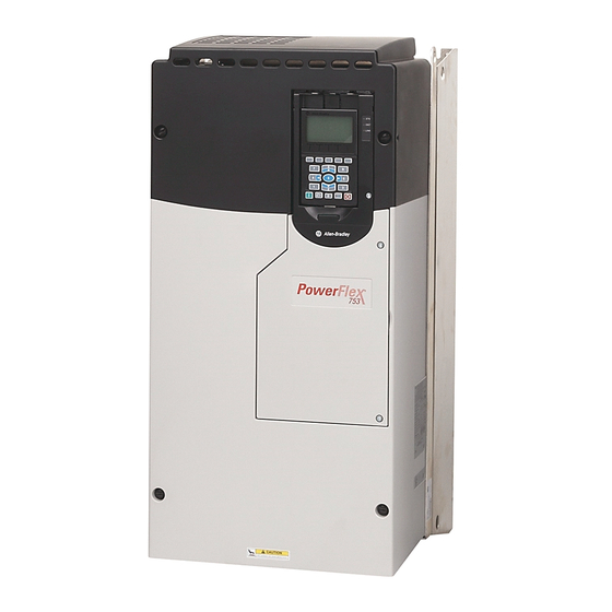
Allen-Bradley PowerFlex 750 Series Manuals
Manuals and User Guides for Allen-Bradley PowerFlex 750 Series. We have
7
Allen-Bradley PowerFlex 750 Series manuals available for free PDF download: Programming Manual, User Manual, Installation Instructions Manual, Installation Instructions
Allen-Bradley PowerFlex 750 Series Programming Manual (548 pages)
Brand:
Allen-Bradley
| Category:
Controller
| Size: 40 MB
Table of Contents
Table of Contents
3
Manual Conventions
7
Preface
7
Product Certification
7
Summary of Changes
7
General Precautions
8
Additional Resources
10
Chapter 1 Start-Up Check List
13
Startup
13
Start-Up Menu
15
Drive Status Indicators
16
Establishing a Connection with Ethernet/Ip
17
Parameter Organization
19
Chapter 2 About Parameters
20
Parameter Access Level
21
How Drive Parameters Are Organized
22
How Option Module Parameters Are Organized
42
Drive Port 0 Parameters
47
Chapter 3 Drive (Port 0) Monitor File
48
Drive (Port 0) Motor Control File
50
Drive (Port 0) Feedback & I/O File
64
Drive (Port 0) Cfg File
80
Drive (Port 0) Protection File
95
Drive (Port 0) Speed Control File
108
Drive (Port 0) Torque Control File
123
Drive (Port 0) Position Control File
130
Drive (Port 0) Communication File
145
Drive (Port 0) Diagnostics File
152
Drive (Port 0) Applications File
171
Chapter 4 Inverter (Port 10) Common Parameters
212
Port 10 and Port 11 Parameters
212
Inverter N (Port 10) Parameters
214
Converter (Port 11) Common Parameters
217
Converter N (Port 11) Parameters
220
Precharge (Port 11) Common Parameters
223
Precharge N (Port 11) Parameters
225
Embedded Ethernet/Ip (Port 13) Parameters
230
Chapter 5
236
Communication Configurations
236
Embedded Devicelogix (Port 14) Parameters
239
11-Series I/O Module Parameters
242
22-Series I/O Module Parameters
252
Single Incremental Encoder Module Parameters
263
Dual Incremental Encoder Module Parameters
266
Universal Feedback Module Parameters
271
Safe Speed Monitor Module Parameters
289
Chapter 6 Faults, Alarms, and Configurable Conditions
301
Drive Status Indicators
303
HIM Indication
305
Manually Clearing Faults
305
Power Layer Interface (PLI) Board 7-Segment Display
306
Setting Factory Defaults
307
System Resource Allocation
307
Fault and Alarm Display Codes
308
Hardware Service Manual
308
Integrated Motion Applications
308
Parameter Access Level
308
Drive Fault and Alarm Descriptions
309
Inverter (Port 10) Faults and Alarms (Frame 8 and Larger)
324
Converter (Port 11) Faults and Alarms (Frame 8 and Larger)
329
Precharge (Port 11) Faults and Alarms (Frame 8 and Larger)
334
N-1 and Re-Rate Functions
337
Embedded Ethernet/Ip (Port 13) Events
341
I/O Faults and Alarms
343
Safe Torque off Fault
343
ATEX Faults
344
Single Incremental Encoder Faults and Alarms
344
Dual Incremental Encoder Faults and Alarms
345
Universal Feedback Faults and Alarms
346
Common Symptoms and Corrective Actions
353
Port Verification
353
External Brake Resistor
356
Powerflex 755 Lifting/Torque Proving
356
Technical Support Options
357
Rockwell Automation Publication 750-PM001N-EN-P - February
358
Appendix A
360
Diagram Conventions and Definitions
360
Diagrams
360
Diagrams
361
Diagrams
362
Diagrams
363
Diagrams
364
Diagrams
365
Diagrams
366
Diagrams
367
Diagrams
368
Diagrams
369
Diagrams
370
Diagrams
371
Diagrams
372
Diagrams
373
Diagrams
374
Diagrams
375
Diagrams
376
Diagrams
377
Diagrams
378
Diagrams
379
Diagrams
380
Diagrams
381
Diagrams
382
Diagrams
383
Diagrams
384
Diagrams
385
Diagrams
386
Diagrams
387
Diagrams
388
Diagrams
389
Diagrams
390
Diagrams
391
Diagrams
392
Diagrams
393
Diagrams
394
Diagrams
395
Diagram Conventions and Definitions
396
Diagrams
397
Diagrams
398
Diagrams
399
Diagrams
400
Diagrams
401
Diagrams
402
Diagrams
403
Diagrams
404
Diagrams
405
Diagrams
406
Diagrams
407
Diagrams
408
Diagrams
410
Diagrams
411
Diagrams
412
Diagrams
413
Diagrams
414
Diagrams
415
Diagrams
416
Diagrams
417
Diagrams
418
Diagrams
419
Diagrams
420
Diagrams
421
Diagrams
422
Diagrams
423
Diagrams
424
Diagrams
425
Diagrams
426
Diagrams
427
Diagrams
428
Diagrams
429
Diagrams
430
Diagrams
431
Diagrams
432
Diagrams
433
Diagrams
434
Diagrams
435
Diagrams
436
Diagrams
437
Diagrams
438
Appendix B Voltage Tolerance
439
Powerflex 755 Lifting/Torque Proving
440
Crane Set up with Encoder Feedback
442
Crane Setup - Encoderless
451
Pump off Function
459
Predictive Maintenance with Logix
471
Appendix D Introduction
479
Function Block Elements
481
Parameters
481
Bit and Analog I/O Points
482
Tips
484
Program Examples
486
Compatible Allen-Bradley Servo Motors
497
Appendix E
501
Appendix F
501
Introduction
501
Feedback Configuration Options
503
Torque Prove and Brake Slip Detect
507
Powerflex 755 Integrated Motion Using Firmware
511
Revision 12.001 or Later
511
Parameter / Instance Attribute Mapping
513
Enhanced Attributes
520
Faults
527
Additional Resources
530
Index
531
Diagrams
532
Advertisement
Allen-Bradley PowerFlex 750 Series User Manual (50 pages)
ATEX Option Module
Brand:
Allen-Bradley
| Category:
Control Unit
| Size: 6 MB
Table of Contents
Table of Contents
3
Preface
5
Summary of Changes
5
About the Powerflex 750-Series ATEX Option Module
7
Catalog Numbers for ATEX and 11-Series I/O Option Modules
7
Catalog Numbers for Spare Terminal Plugs
7
Additional Resources
8
Chapter 1 ATEX Directive 2014/34/EU
9
Safety Concepts
9
Motor Requirements
10
ATEX Function
11
Thermostat Trip
12
Positive Temperature Coefficient (PTC) Trip
12
ATEX System
11
Safe State
12
Contact Information if Safety Option Failure Occurs
13
Hardware Fault Tolerance
13
Safety Reaction Time
13
Chapter 2 Perform a Risk Assessment of the Operational Environment
15
Installation and Wiring
15
Access the Drive Control Pod
16
Remove the Drive Cover for Frame 1
16
Remove the Drive Cover for Frames 2
17
Remove the Drive Cover for Frames 6 and 7
18
Remove the Drive Cover for Frames 8
19
Perform a Safety Analysis of the Motor
16
Configure the Hardware
21
S1 Switch Location
21
Safety Enable Jumper Locations
22
ATEX Option Module and 11-Series I/O Option Module
23
Without a Safety Option Module
23
With a Safety Option Module
24
Assemble the ATEX and 11-Series I/O Option Modules
25
Connect the Thermal Sensor Wires
26
Cabling Requirements
26
Installation Requirements
27
Install the ATEX Option Module Assembly
27
Safe Torque off Option Wiring
30
Safe Speed Monitor Option Wiring
31
Interface Without a Safety Option
32
Reset the Drive after an SSM Fault Detection
32
Chapter 3 Description of Functionality
33
Motors with Thermostatic Switches
34
Thermostat Contacts
34
Motors with Positive Temperature Coefficient (PTC) Devices
35
Functional Proof Testing for Systems with PTC Devices
35
Functional Proof Testing Without a Test Fixture
36
Chapter 4 Parameter 41 [ATEX Sts]
39
ATEX Configuration Errors
40
ATEX Fault Descriptions
40
Restart the Drive after an Over-Temperature Fault
41
11-Series I/O Option Module Terminal Block Specifications
43
Appendix A
43
General Specifications
43
Environmental Specifications
44
Safety Data
44
Certifications
45
Index
47
Rockwell Automation Publication 750-UM003D-EN-P - March
48
Allen-Bradley PowerFlex 750 Series Installation Instructions Manual (32 pages)
Service Cart and DC Precharge Module Lift
Brand:
Allen-Bradley
| Category:
Outdoor Cart
| Size: 9 MB
Table of Contents
Table of Contents
1
Summary of Changes
1
Before You Begin
2
Setup the Service Cart
4
Adjust the Service Cart
7
Remove the Power Module
8
Use the DCPC Module Lift (Optional)
13
Remove the DC Precharge Module (Optional)
14
Move the Power Module and the DC Precharge Module
16
Unload, Load, and Store the Power Module
19
Return the Power Module and the DC Precharge Module into the Cabinet
22
Storage, Maintenance, and Customer Support
29
Additional Resources
30
Advertisement
Allen-Bradley PowerFlex 750 Series Installation Instructions Manual (12 pages)
Brand:
Allen-Bradley
| Category:
Controller
| Size: 4 MB
Allen-Bradley PowerFlex 750 Series Installation Instructions Manual (6 pages)
DC Bus Bars – Frame 6 and 7
Brand:
Allen-Bradley
| Category:
Controller
| Size: 6 MB
Allen-Bradley PowerFlex 750 Series Installation Instructions Manual (6 pages)
Power Jumpers
Brand:
Allen-Bradley
| Category:
Controller
| Size: 1 MB
Allen-Bradley PowerFlex 750 Series Installation Instructions (2 pages)
Option Modules
Brand:
Allen-Bradley
| Category:
I/O Systems
| Size: 1 MB
Table of Contents
Compatible Ports
1
Option Module Installation Using 20-750-S1 with 20-750-DENC-1
1
Auxiliary Power Supply (20-750-APS) Installation
2
Option Module Installation Next to a Profibus Option Module
2
Advertisement
Related Products
Allen-Bradley PowerFlex 753
Allen-Bradley PowerFlex 755
Allen-Bradley PowerFlex 755T
Allen-Bradley PowerFlex 755TL
Allen-Bradley PowerFlex 755TR
Allen-Bradley PowerFlex 755TM
Allen-Bradley PowerFlex 755 IP00
Allen-Bradley PowerFlex 700 AFE
Allen-Bradley PowerFlex 700SE
Allen-Bradley 7762
Allen-Bradley Categories
Control Unit
Controller
I/O Systems
Power Supply
Switch
More Allen-Bradley Manuals
Login
Sign In
OR
Sign in with Facebook
Sign in with Google
Upload manual
Upload from disk
Upload from URL