Sign In
Upload
Manuals
Brands
Allen-Bradley Manuals
Controller
PowerFlex 700 AFE
Allen-Bradley PowerFlex 700 AFE Manuals
Manuals and User Guides for Allen-Bradley PowerFlex 700 AFE. We have
2
Allen-Bradley PowerFlex 700 AFE manuals available for free PDF download: Hardware Service Manual, Migration Manual
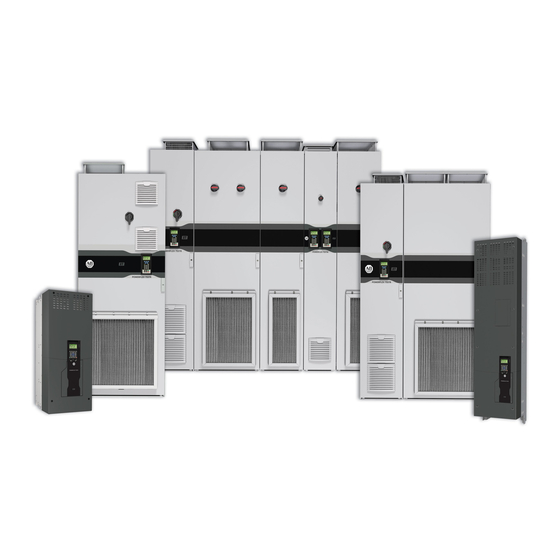
Allen-Bradley PowerFlex 700 AFE Hardware Service Manual (134 pages)
PowerFlex Active Front End – AFE Frame 10 system
Brand:
Allen-Bradley
| Category:
Controller
| Size: 15.64 MB
Table of Contents
Table of Contents
3
Intended Audience
7
Preface
7
Summary of Changes
7
What Is in this Manual
7
What Is Not in this Manual
7
Additional Resources
8
Additional Support Available on the Internet
8
Spare Parts
8
General Precautions for Class 1 Light-Emitting Diode Product
9
Chapter 1 Troubleshooting and Error Codes Create Fault Reports
12
Create Fault Reports
12
Powerflex Active Front End Faults
12
Common Symptoms and Corrective Actions
17
Chapter 2
19
Main Component Sections
19
Main Component Locations
20
Main Bus Bar/Cable Locations
21
AFE in IP21 Rittal Enclosure
22
Main Component Sections
22
Main Component Locations
23
Bus Bar Locations
24
AFE in IP00 Open Chassis Configuration
25
AFE in IP20 2500 MCC Style Enclosure
19
Chapter 3 Perform a Visual Inspections
28
Inspect the Cooling Tunnel
28
Component Test Procedures View the Status Indicators
28
Inspect the Power Structure
29
View the Status Indicators
28
Perform Forward and Reverse Biased Diode Tests for Power Structure
29
Check Fiber-Optic Connections
31
Perform Gate Driver Board Resistance Measurements
33
Check the AFE Power Structure Fan Inverter Fuses
34
Chapter 4
36
Torque Specifications
36
Understand Torque Figures in Assembly Diagrams
36
Remove Power from the AFE
37
Control Frame Access Procedures
38
Remove the DPI Interface Assembly
38
Install the DPI Interface Assembly
39
Remove the I/O Circuit Boards and Control Board
39
Install the I/O Circuit Boards and Control Board
40
Remove the Fiber-Optic Adapter Circuit Board
40
Install the Fiber-Optic Adapter Circuit Board
42
Remove the Control Frame
43
Rittal Enclosure)
43
Replace the Control Frame
43
Power Structure Access Procedures
44
Remove AFE Protective Barriers
44
Install the AFE Protective Barriers
45
Remove the AFE Airflow Plate
45
Install the AFE Airflow Plate
45
Remove Protective Covers from the Power Structure
46
Install Protective Covers on the Power Structure
46
Remove the Gate Driver Circuit Board
46
Install the Gate Driver Circuit Board
48
Remove the ASIC Circuit Board
48
Install the ASIC Circuit Board
51
Remove and Install the Power Structure Fan System
52
Remove the Power Structure from the Enclosure
52
Install the Power Structure in the Enclosure
55
Remove the Power Module from the Power Structure
55
Install the Power Module on the Power Structure
61
Remove the Power Structure DC Bus Capacitors
61
Install the Power Structure DC Bus Capacitors
62
Power Structure
62
AC Line Switchgear Component Section
63
AFE in IP20 2500 MCC Style Enclosure
64
AFE in IP21 Rittal Enclosure
64
Chapter 5
64
Precharge Component Section
65
Chapter 6 Precharge Functions
66
Replace the Precharge Fuse
66
Supply (T10)
67
For AFE in IP20 2500 MCC Style Enclosure
67
For AFE in IP21 Rittal Enclosure
68
Test the Control Transformer (T4) and 24V DC Power
67
Replace the Precharge Bridge
70
Terminals
70
Test the Precharge Bridge by Using the Power Structure
70
Replace the Precharge Resistor Assembly
71
AFE in IP20 2500 MCC Style Enclosure
71
AFE in IP21 Rittal Enclosure
72
Rockwell Automation Publication 20Y-TG001C-EN-P - April
73
Test the Precharge Resistor
71
Chapter 7
74
Install the LCL Filter Protective Barrier
74
Remove the LCL Filter Protective Barrier
74
Replace the LCL Filter DC Fan Fuses
74
Remove the LCL Filter Fan DC Power Supply
75
Install the LCL Filter Fan DC Power Supply
77
Remove the LCL Filter
78
From the IP20 2500 MCC Style Enclosure
79
From the IP21 Rittal Enclosure
80
Replace the LCL Filter Fan
78
Install the LCL Filter in the Enclosure
81
Overview
83
Chapter 8 Fuse Replacement Guidelines
84
Chapter 9 Technical Support
87
Before You Apply Power to the AFE
88
Appendix A
89
Service Tools
89
Software Tools
89
Appendix B Frame 10 Circuit Board Connections
91
Frame 10 Power Module Circuitry
92
Frame 10 Power Structure Main Fan Connections
93
Control Wiring Diagram for Frame 10 in IP20 2500
94
MCC Style Enclosure
94
MCC Style Enclosure
96
Control Wiring Diagram for Frame 10 in IP21 Rittal Enclosure
103
System Schematics for Frame 10 AFE in IP21 Rittal Enclosure
104
Circuit Board Connections
113
Appendix C Hardware Connections
116
AFE Power Structure Assembly
118
Appendix D
122
LCL Filter Assembly (Used in IP20 and IP21 Enclosures)
122
Precharge Assembly
124
AC Line Switchgear
126
Data to Collect
129
Typical Transformer Winding Types
130
Index
131
Advertisement
Allen-Bradley PowerFlex 700 AFE Migration Manual (102 pages)
Regenerative Bus Supply
Brand:
Allen-Bradley
| Category:
Power Supply
| Size: 10.47 MB
Table of Contents
Table of Contents
3
Overview
5
Preface
5
General Precautions
6
Parameter References
6
Compatibility Quick Check
7
Before Migration
8
General Information
8
Abbreviations
9
Additional Resources
10
Selection Considerations
13
Chapter 1 About the Powerflex 700AFE Bus Supply
14
Powerflex 700AFE Catalog Number Explanation
15
About the Powerflex 755TM Bus Supply
16
Powerflex 755T Product Catalog Number Explanation
17
Power and Control Bus Bar Ratings
20
Power Source Considerations
21
Sizing
21
Other Loads Powered from the AFE AC Power Source
22
Power Source Grounding
22
Recommended Grounding Scheme
24
Bus Capacitance and Precharging Consideration
24
EMI Filters
26
Power Filter Jumpers
26
Circuit Protection
27
Check Example
28
AC Power Cables
29
Other Power Circuit Considerations
29
Control Power
30
Specification and Feature Comparison
33
Cross Reference Guides
41
Dimensional Cross Reference
45
Device Ports and Main Control Board I/O
50
Powerflex 700AFE Bus Supply
50
Powerflex 755TM Bus Supply
52
Hardware Enable Circuits
55
Customer Power Terminal Comparison
56
Locations and Specifications
56
Powerflex 755TM Bus Supply Customer Power Terminal
60
Locations and Specifications
60
Control Terminal Comparison
64
Powerflex 700AFE Digital and Analog I/O
64
Powerflex 755TM Bus Supply I/O Option Modules
65
Configuration Software and HIM Versions
67
Chapter 2 Parameter Comparison
68
Powerflex 700AFE Parameter Assignment
68
Assignment
68
Bus Supply Hardware Configuration
72
Powerflex 700AFE Bus Supply Control Devices
72
Powerflex 755TM Bus Supply Control
75
Chapter 3
80
Compatibility
80
Scaling of Reference and Feedback
81
Powerflex 700AFE DPI Communications
81
Powerflex 755TM Bus Supply Communications
82
Logic Command Word Comparison
83
Datalink Handling Comparison
84
16-Bit Processors (PLC-5, SLC 500, and Micrologix 1100/1400)
85
Powerflex 755T 20-COMM-X Network Adapter
80
Appendix A Dimension and Enclosure Types
87
Cooling and Airflow Comparison
90
Powerflex 700AFE Installation Requirements
90
Powerflex 755TM Bus Supply Installation Requirements
95
Powerflex 755T Product Equipment Handling Options
99
Module Service Cart
99
DC Precharge Module Service Lift
99
Power Module Service Ramp
99
Power and Filter Module Storage Hardware
99
IP00 Open Type Power Structures
100
Advertisement
Related Products
Allen-Bradley powerflex 700
Allen-Bradley PowerFlex 700S
Allen-Bradley PowerFlex 700L
Allen-Bradley PowerFlex 700H
Allen-Bradley PowerFlex 700SE
ALLEN BRADLEY PowerFlex 7000
Allen-Bradley PowerFlex 755TR
Allen-Bradley 7761
Allen-Bradley PowerFlex 755 IP00
Allen-Bradley 7760
Allen-Bradley Categories
Control Unit
Controller
I/O Systems
Power Supply
Switch
More Allen-Bradley Manuals
Login
Sign In
OR
Sign in with Facebook
Sign in with Google
Upload manual
Upload from disk
Upload from URL