Sign In
Upload
Manuals
Brands
Agilent Technologies Manuals
Test Equipment
U1604A
Agilent Technologies U1604A Manuals
Manuals and User Guides for Agilent Technologies U1604A. We have
3
Agilent Technologies U1604A manuals available for free PDF download: User's And Service Manual, Quick Start Manual
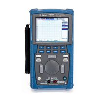
Agilent Technologies U1604A User's And Service Manual (210 pages)
Handheld Digital Oscilloscopes
Brand:
Agilent Technologies
| Category:
Test Equipment
| Size: 6.05 MB
Table of Contents
Table of Contents
17
1 Getting Started
29
To Inspect Package Contents
30
Figure 1-1 Standard Shipped Components
31
Figure 1-2 Optional Accessories
32
Table 1-1 Power Cord Types
32
To Charge a Battery
33
Figure 1-3 Battery Charging
33
To Power-On Instrument
34
To Reset to Default Factory Settings
34
Figure 1-4 Factory Setup
35
To Perform Self-Calibration
36
To Set Date and Time
37
Figure 1-5 Self-Calibration Dialog Box
37
Figure 1-6 Select the Date Format
38
Figure 1-7 Date and Time Setting
38
To Set Auto-Power off
39
Figure 1-8 Auto-Power off Function
39
To Select Quick Help Language
40
To Adjust Contrast of Display
41
To Compensate Scope Probe
42
Figure 1-9 Adjust Display Contrast
42
Figure 1-10 Connection for Scope Probe Compensation
43
Figure 1-11 a 10X Scope Probe with over Compensation, Adjust the Trimmer Capacitor to Obtain the Flattest Pulse Possible as Shown in Figure
43
Figure 1-12 Trimmer Capacitor for Probe Compensation
44
Figure 1-13 Pulse Shape Reference for Scope Probe Compensation
44
2 Front Panel and Displays Overview
45
Front Panel Overview
45
Figure 2-1 U1600A Series Handheld Digital Oscilloscope Front Panel
48
Oscilloscope Display Overview
50
Figure 2-2 Interpreting Scope Display
50
Multimeter Display Overview
52
Figure 2-3 Interpreting Meter Display
52
3 Using the Scope Functions
53
Vertical Controls
54
Channel Selection for Waveform Display
54
Figure 3-1 Scope Menu Display with Displayed of both Channels Display
54
Figure 3-2 Select on or off to Enable or Disable the Waveform Display
55
Vertical System Setup
56
To Change Vertical Reference Ground Position
56
Figure 3-3 Adjust Vertical Position for the Waveform Displayed
56
To Center the Waveform on the Display
57
Figure 3-4 Reset Vertical Ground Reference Symbol to Zero Volt
57
To Change Vertical Sensitivity
58
Figure 3-5 Vertical Sensitivity Display
58
Channel Coupling Control
59
AC Channel Coupling
59
Figure 3-6 AC Channel Coupling
59
DC Channel Coupling
60
Ground Channel Coupling
60
Figure 3-7 DC Channel Coupling
60
Figure 3-8 Gnd Channel Coupling
60
Probe Attenuation Control
61
Figure 3-9 Probe Attenuation Scale Setting
61
Invert Control
62
Figure 3-10 the Waveform before Inversion
62
Figure 3-11 the Waveform after Inversion
63
Horizontal Controls
64
Vertical System Setup
64
To Change Horizontal Scale Factor
64
Figure 3-12 Time/DIV Display in Status Line
64
To Set Delay of the Waveforms
65
Figure 3-13 Changing Time Base of a Waveform
65
To Change Trigger Point Indicator
66
Horizontal Mode Functions
67
Time Base Mode
67
Figure 3-14 Select Time Reference
67
Main/Zoom Mode
68
Figure 3-15 XY Format Display
68
Figure 3-16 When Window Function Is Turned On, a Zoom Area Selection Bar Appears at the Center of the Display. Adjust Rotary Switch Clockwise to Expand the Zoom Area
69
Roll Mode
70
Figure 3-17 Press F1 to Enable Zooming Function
70
Trigger Controls
71
Trigger Modes
71
Figure 3-18 Normal Trigger Mode
71
Auto Trigger Mode
72
Normal Trigger Mode
72
Single Trigger Mode
72
Trigger Types
73
Edge Trigger
73
Pattern Trigger
76
Video Trigger
79
Waveform Controls
80
Normal Acquisition Mode
81
Average Acquisition Mode
81
Figure 3-19 Normal Acquisition Mode
81
Peak Detection Mode
82
Figure 3-20 Average Acquisition Mode
82
Figure 3-21 Peak Detection Mode
82
Display Controls
83
Display Types
83
Figure 3-22 Dots Display Type
83
Display Contrast
84
Figure 3-23 Vectors Display Type
84
Graticule
85
Persistence
85
Automatic Measurement
86
To Perform Automatic Measurements
87
Time Automatic Measurements
88
Figure 3-24 Select Automatic Measurement for the Measure 1 File
88
Figure 3-25 +Width and -Width Measurements
89
Voltage Automatic Measurements
90
Figure 3-26 Period Measurement
90
Figure 3-27 Voltage Measurement
91
Figure 3-28 Phase Measurement
92
Figure 3-29 Delay Measurement
92
Cursor Measurement Controls
94
Figure 3-30 Cursor Measurement Menu
94
X-Cursor Measurement
95
Figure 3-31 X-Cursor Measurement for Channel 1 Signal with X1 and X2 Cursor
96
Lines
96
Figure 3-32 X-Cursor Measurement for Channel 2 Signal with X1 and X2 Cursor
97
Figure 3-33 Math Functions for X-Cursor Measurement
97
Lines
97
Y-Cursor Measurement
98
Figure 3-34 Y-Cursor Measurement for Channel 1 Signal with Y1 and Y2 Cursor
99
Lines
99
Figure 3-35 Y-Cursor Measurement for Channel 2 Signal with X1 and X2 Cursor
100
Figure 3-36 Math Function for Y-Cursor Measurement
100
Lines
100
Math Functions Control
101
Dual Waveform Math - Add, Subtract
101
Add (CH1 + CH2)
102
Figure 3-37 Addition of Channel 1 and Channel 2 Function
102
Subtraction (CH1 - CH2, CH2 - CH1)
103
Figure 3-38 Subtraction Signal at Channel 2 from Channel 1
103
FFT (Fast Fourier Transform)
104
Save and Recall Controls
106
Save and Recall Controls Without USB Flash Memory Device
106
Figure 3-39 Save/Recall Menu
106
Figure 3-40 the <Save> Display Indicates no Setup File Is Being Saved. You Can Press F1 to Save the Setup into Setup
107
Figure 3-41 the <Load> Display Indicates that a Configuration Setup File Has Been Saved into Setup 1 and You Can Press F1 to Retrieve the Setup from Internal Memory
108
To Save and Recall Waveform
108
Figure 3-42 the <Save> Display Indicates no Waveform Is Being Saved, You Can Press F1 to Save the Waveform into Waveform
109
Figure 3-43 the <Load> Display Indicates the a Waveform File Is Saved into
109
Internal Memory. this Function Is Useful for Waveform Comparison
109
To Erase Setup
110
Figure 3-44 the <None> Display Indicates that no Setup File Is Saved. the <Erase> in Setup 1 Shows that You Can Erase the Setup File from the Internal Memory
110
To Erase Waveform
111
Figure 3-45 the <None> Display Indicates that no Waveform Is Being Saved. the <Erase> in Waveform 1 Shows that You Can Erase the Waveform from the Internal Memory
111
To Restore Factory Setup
112
Figure 3-46 Restore Factory Setup in Save/Load Setup Menu
113
Figure 3-47 the Instrument Requests Confirmation to Restore Factory Default
113
Save and Recall Controls with USB Flash Memory Device
114
Figure 3-48 Connect a USB Flash Memory to Save or Download Waveforms To/From the External Memory Device
114
To Load Waveform
115
To Save Waveform
115
Figure 3-49 Load a Waveform from a USB Flash Memory Device
116
To Clear Waveform
116
To Erase Waveform
116
Autoscale and Run/Stop Controls
117
Autoscale
117
Table 3-1 Autoscale Conditions
117
Run/Stop Controls
118
Figure 3-50 Run and Stop Modes
118
Utility Controls
119
Auto-Power off Control
119
Figure 3-51 Auto-Power off Control
119
Language Selection
120
USB Flash Memory On/Off
120
Date and Time Setting
120
Self-Calibration
120
Probe Calibration
121
Low Battery Mode
121
Figure 3-52 Message Display During Low Battery Condition
121
Mute Function
122
4 Using the Digital Multimeter Functions
123
Voltmeter
124
Figure 4-1 Multimeter Display
124
Figure 4-2 DC Measurement Display
125
Ohmmeter
126
Resistance Measurement
126
Figure 4-3 Resistance Measurement
127
Continuity Test
128
Figure 4-4 Continuity Test Shorted with Audible Beeper Sound
128
Diode Test
129
Figure 4-5 Diode in Forward Bias Condition
130
Figure 4-6 Diode in Open Condition
130
Capacitance Measurement
131
Figure 4-7 Capacitance Measurement
131
Auxiliary Meter
132
Temperature Meter
132
Figure 4-8 Temperature Measurement in Degrees Celsius (°C) Together with Degree Fahrenheit (°F) Display
133
Ampere Meter
134
Humidity Meter
135
Figure 4-9 Current Measurement
135
Pressure Meter
136
Figure 4-10 Humidity Measurement
136
Figure 4-11 Pressure Measurement
137
Relative Function
138
Figure 4-12 Set the Reading as Reference Value
138
Figure 4-13 Set the Reading as Measured Value
139
Figure 4-14 Relative Value Obtained from the Delta of the Measured and
139
Automatic Measurement in Multimeter Mode
140
Figure 4-15 Automatic Measurement in Resistance Measurement Mode
140
Restart Test
141
Auto-Range Mode
141
Figure 4-16 Auto-Range Mode
142
Figure 4-17 Manual Range Mode
142
5 Using the Data Logger Functions
143
The U1600A Series Handheld Digital Oscilloscope Is Equipped with
143
Data Logger Function
144
Figure 5-1 Maximum Measurement Is Selected for Resistance Data Recording
146
Figure 5-2 after Exceeding 150 Seconds, the Graph Automatically Compresses to Half Screen and the Time Base Changes to 30 Seconds
146
Figure 5-3 Maximum Measurement Is Selected for DC Voltage Data Recording
147
Figure 5-4 after Exceeding 150 Seconds, the Graph Automatically Compresses to Half Screen and the Time Base Changes to 30 Seconds
147
Automatic Measurement in Data Logger Mode
148
Restart Test
148
6 Service and Maintenance
149
Warranty Services
149
Standard Warranty (Worldwide)
149
Accessories Warranty
151
Returning Instrument to Agilent Technologies for Service
152
Cleaning
153
Basic Troubleshooting Hints
153
7 Performance Tests
156
List of Test Equipment
158
Table 7-1 List of Test Equipments for Scope Performance Test
158
Table 7-2 List of Test Equipment for Multimeter Performance Test
159
Oscilloscope Performance Verification Tests
160
Voltage Measurement Accuracy Verification Test
160
Table 7-3 Settings Used to Verify Voltage Measurement Accuracy
161
Figure 7-5 Test Connection from Calibrator to Instrument and Digital Multimeter
162
Bandwidth Verification Test
163
Table 7-4 Signal Generator Frequency Setting
164
Horizontal Δt and 1/Δt Accuracy Verification Test
165
Trigger Sensitivity Verification Test
166
Multimeter Performance Verification Tests
168
DC Voltage Verification Test
168
Figure 7-6 Test Connections from Calibrator to Instrument
169
Table 7-5 DC Volts Verification Test
169
AC Voltage Verification Test
170
Table 7-6 AC Volts Verification Test
170
Resistance Verification Test
171
Table 7-7 Resistance Verification Test
171
Capacitance Verification Test
172
Table 7-8 Capacitance Verification Test
172
Diode Verification Test
173
Table 7-9 Diode Verification Test
173
Continuity Verification Test
174
Self-Calibration
175
Self-Calibration Error Code
176
Figure 7-7 Self-Calibration Dialog Box
176
Table 7-10 Self-Calibration Error Code
177
AC Current Verification Test
178
Temperature Verification Test
179
Agilent U1602A/U1604A Handheld Digital Oscilloscope Test Record
179
8 General Disassemble
182
Mechanical Disassemble
183
To Remove Stand
184
Figure 8-1 Push Towards the Arrow Direction to Remove the Stand
184
Figure 8-2 Disassemble the Stand from the Instrument
184
To Remove Battery Pack
185
Figure 8-3 Remove Battery Cover Screw
185
To Replace Battery Pack
186
Figure 8-4 Unplug 3-Wire Connector from PCBA Board Using Tweezer
186
Figure 8-5 Remove Battery Pack Cover Without Removing Stand
187
Figure 8-6 Unplug 2-Wire Connector with a Tweezer
187
To Remove Handler
189
Figure 8-7 Remove Screw from the Rear Cover
189
Figure 8-8 Remove Handler from the Instrument
189
To Remove Front and Rear Casing
190
Figure 8-9 Remove and Keep the above Wear-And-Tear Parts for Re-Assemble
190
Figure 8-10 Remove Front Casing (Right) and Rear Casing (Left) from PCBA of the
191
Instrument
191
To Remove Keypad
192
To Dismantle System Boards
193
To Remove LCD Display
194
Replacement Parts
195
Table 8-1 Replacement Part List
195
9 Characteristics and Specifications
196
Specifications
197
Table 9-1 Warranted Specifications
197
Characteristics
199
Table 9-2 Characteristics
199
General Characteristics
204
Table 9-3 General Characteristics
204
Environmental Conditions
205
Pollution Degree
205
Pollution Degree Definitions
205
Measurement Category
206
Measurement Category Definitions
206
Index
208
Advertisement
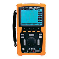
Agilent Technologies U1604A User's And Service Manual (227 pages)
Handheld Digital Oscilloscopes
Brand:
Agilent Technologies
| Category:
Test Equipment
| Size: 4.77 MB
Table of Contents
Table of Contents
17
Safety Summary
6
Safety Symbols
7
General Safety Information
9
Figures
25
Table of Contents
31
1 Getting Started
33
To Charge a Battery
33
To Power on Instrument
33
To Inspect Package Contents
34
Standard Shipped Components
35
Optional Accessories
36
Power Cord Types
36
To Charge a Battery
37
Battery Charging
38
To Power on Instrument
39
To Reset to Default Factory Settings
39
Factory Setup
40
To Perform Self-Calibration
41
To Set Date and Time
42
Self-Calibration Dialog Box
42
Select the Date Format
43
Date and Time Setting
43
To Set Auto-Power off
44
Auto-Power off Function
44
To Select Quick Help Language
45
To Adjust Contrast of Display
46
Adjust Display Contrast
46
To Compensate Scope Probe
47
Connection for Scope Probe Compensation
47
Figure 1-11. a 10X Scope Probe with over Compensation, Adjust the
48
Front Panel and Displays Overview
51
Front Panel Overview
51
Multimeter Display Overview
51
2 Front Panel and Displays Overview
52
Front Panel Overview
52
Oscilloscope Display Overview
57
Multimeter Display Overview
59
3 Using the Scope Functions
61
Vertical Controls
62
Channel Selection for Waveform Display
62
Vertical System Setup
64
To Change Vertical Reference Ground Position
64
To Center the Waveform on the Display
65
To Change Vertical Sensitivity
66
Channel Coupling Control
67
AC Channel Coupling
67
DC Channel Coupling
68
Ground Channel Coupling
68
Probe Attenuation Control
69
Invert Control
70
Horizontal Controls
72
Vertical System Setup
72
To Change Horizontal Scale Factor
72
To Set Delay of the Waveforms
73
To Change Trigger Point Indicator
74
Horizontal Mode Functions
75
Time Base Mode
75
Main/Zoom Mode
76
Roll Mode
78
Trigger Controls
79
Trigger Modes
79
Auto Trigger Mode
80
Normal Trigger Mode
80
Single Trigger Mode
80
Trigger Types
81
Edge Trigger
81
Pattern Trigger
84
Video Trigger
87
Average Acquisition Mode
88
Average Acquisition Mode
89
Normal Acquisition Mode
89
Peak Detection Mode
90
Waveform Controls
88
Display Controls
91
Display Types
91
Display Contrast
92
Graticule
93
Persistence
93
Automatic Measurement
94
To Perform Automatic Measurements
95
Time Automatic Measurements
96
Duty
96
Width
97
Frequency
97
Rise Time
97
Fall Time
98
Period
98
Voltage Automatic Measurements
98
Mean
98
Mean Cycle
98
Amplitude
98
Top
98
Base
99
Maximum
99
Minimum
99
Peak-To-Peak
99
Phase and Delay
100
Phase
100
Delay
101
Preshoot and Overshoot
101
Preshoot
101
Overshoot
102
Cursor Measurement Controls
103
X-Cursor Measurement
104
Y-Cursor Measurement
107
Math Functions Control
110
Dual Waveform Math - Add, Subtract
110
Add (CH1 + CH2)
111
Subtraction (CH1 - CH2, CH2 - CH1)
112
FFT (Fast Fourier Transform)
113
Source
113
Axis
113
Window
114
Save and Recall Controls
115
Save and Recall Controls Without USB Flash Memory Device
116
To Save and Recall Waveform
118
To Erase Setup
120
To Erase Waveform
121
To Restore Factory Setup
122
Save and Recall Controls with USB Flash Memory Device
124
To Save Waveform
125
To Load Waveform
125
To Erase Waveform
126
To Clear Waveform
127
Autoscale and Run/Stop Controls
128
Autoscale
128
Autoscale Conditions
128
Run/Stop Controls
129
Utility Controls
130
Auto-Power off Control
130
Language Selection
131
USB Flash Memory On/Off
131
Date and Time Setting
131
Self-Calibration
131
Probe Calibration
132
Low Battery Mode
132
Mute Function
133
4 Using the Digital Multimeter Functions
135
4 Using the Digital Multimeter Functions
136
Voltmeter
136
Ohmmeter
138
Resistance Measurement
138
Relative Function
138
Continuity Test
138
Diode Test
138
Continuity Test
140
Diode Test
141
Capacitance Measurement
143
Auxiliary Meter
144
Temperature Meter
144
Ampere Meter
146
Humidity Meter
147
Pressure Meter
148
Relative Function
150
Automatic Measurement in Multimeter Mode
152
Restart Test
153
Auto-Range Mode
153
5 Using the Data Logger Functions
155
Restart Test
155
Data Logger Function
155
Automatic Measurement in Data Logger Mode
155
Data Logger Function
156
Automatic Measurement in Data Logger Mode
159
CSV Saving Function and Interval Setting
159
Restart Test
160
6 Service and Maintenance
162
Warranty Services
162
Standard Warranty (Worldwide)
162
Accessories Warranty
163
Standard Calibration Service (Optional)
163
Returning Instrument to Agilent Technologies for Service
164
Cleaning
165
Basic Troubleshooting Hints
165
7 Performance Tests
170
Performance Test Interval
171
Performance Test Record
171
Warming up before Testing
171
List of Test Equipment
172
List of Test Equipments for Scope Performance
172
List of Test Equipment for Multimeter Performance
173
Oscilloscope Performance Verification Tests
174
Voltage Measurement Accuracy Verification Test
174
Settings Used to Verify Voltage Measurement
175
Bandwidth Verification Test
177
Signal Generator Frequency Setting
178
Horizontal Dt and 1/Dt Accuracy Verification Test
179
Trigger Sensitivity Verification Test
180
Multimeter Performance Verification Tests
182
DC Voltage Verification Test
182
DC Volts Verification Test
183
AC Voltage Verification Test
184
AC Volts Verification Test
184
Resistance Verification Test
185
Capacitance Verification Test
186
Diode Verification Test
187
Continuity Verification Test
188
Self-Calibration
189
Self-Calibration Error Code
190
Self-Calibration Error Code
191
8 General Disassemble
196
Mechanical Disassemble
197
To Remove Stand
198
To Remove Battery Pack
199
To Replace Battery Pack
200
To Remove Handler
203
To Remove Front and Rear Casing
204
To Remove Keypad
206
To Dismantle System Boards
207
To Remove LCD Display
208
Replacement Parts
209
Replacement Part List
209
9 Characteristics and Specifications
210
Characteristics
210
Environmental Conditions
210
Specifications
211
Warranted Specifications
211
Characteristics
214
Sampling Rate
219
General Characteristics
220
Environmental Conditions
222
Pollution Degree
222
Measurement Category
223
Measurement Category Definitions
223
Agilent Technologies U1604A Quick Start Manual (18 pages)
Handheld Digital Oscilloscopes
Brand:
Agilent Technologies
| Category:
Test Equipment
| Size: 0.6 MB
Table of Contents
Safety Information
2
Table of Contents
4
Introduction
5
The Front Panel at a Glance
5
Getting Started
6
To Inspect Package Contents
6
To Charge a Battery
7
To Power on the Handheld Scope
7
To Reset to Factory Default Setting
7
To Perform Self-Calibration
7
To Set Time and Date
7
To Set Auto Power off
7
To Select Language for Quick Help
8
To Adjust Contrast of Display
8
To Compensate Scope Probe
8
Scope Screen Display
9
Scope Connection Configuration
10
Meter Connection Configuration
11
Cursor Measurement
12
Save/Recall Setup and Waveform
13
Signal Triggering
13
Automatic Measurements
15
Data Logger
15
Quick Help
15
Advertisement
Advertisement
Related Products
Agilent Technologies U1604B
Agilent Technologies U1602B
Agilent Technologies U1602A
Agilent Technologies U1610/20A
Agilent Technologies U11645A
Agilent Technologies U1091AC50
Agilent Technologies U1091AC80
Agilent Technologies U1091AC83
Agilent Technologies U1452A
Agilent Technologies U1452AT
Agilent Technologies Categories
Measuring Instruments
Laboratory Equipment
Test Equipment
Water Pump
Power Supply
More Agilent Technologies Manuals
Login
Sign In
OR
Sign in with Facebook
Sign in with Google
Upload manual
Upload from disk
Upload from URL