
Related Manuals for Agilent Technologies U1602B


Summary of Contents for Agilent Technologies U1602B
- Page 1 Agilent U1602B and U1604B Handheld Digital Oscilloscopes User’s and Service Guide Agilent Technologies...
-
Page 2: Agilent U1602B/U1604B User's And Service Guide
Should Agilent Technologies, Inc. Agilent and the user have a separate 3501 Stevens Creek Blvd. written agreement with warranty Santa Clara, CA 95052 USA terms covering the material in this... - Page 3 The information contained in this document is subject to change without notice. To the extent allowed by local law, Agilent makes no warranty of any kind with regard to this material, including, but not limited to, the implied warranties of merchantability and fitness for a particular purpose.
- Page 4 (becomes a part of) other Agilent products. During the warranty period, Agilent will, at its option, either repair or replace products which prove to be defective. The warranty period begins on the date of delivery or on the date of installation if installed by Agilent.
- Page 5 Buyer. Agilent does not warrant the Buyer’s circuitry or malfunctions of Agilent products that result from the Buyer’s circuitry. In addition, Agilent does not warrant any damage that occurs as a result of the Buyer’s circuit or any defects that result from Buyer-supplied products.
-
Page 6: Safety Summary
Failure to comply with these precautions or with specific warnings elsewhere in this manual violates safety standards of design, manufacture, and intended use of the instrument. Agilent Technologies, Inc. assumes no liability for the customer’s failure to comply with these requirements. Safety Notices... -
Page 7: Safety Symbols
Direct and alternating current Direct current Equipment protected throughout by DOUBLE INSULATION or REINFORCED INSULATION Caution, hot surface CAT III Measurement category III are measurements performed in the building installation Agilent U1602B/U1604B User’s and Service Guide... - Page 8 The C-tick mark is a registered trademark of the Spectrum Management Agency of Australia. This signifies compliance with the Australia EMC Framework regulations under the terms of the Radio Communication Act of 1992. viii Agilent U1602B/U1604B User’s and Service Guide...
-
Page 9: General Safety Information
Agilent Technologies assumes no liability for the customer’s failure to comply with these requirements. • All DMM/Scope COM are internally connected. Only connect WA R N I N G DMM/Scope COM to same potential. - Page 10 Voltage ratings are Vrms (50 60 Hz) for AC sine wave and VDC for DC applications. Maximum Floating Voltage • From any terminal to ground 300 Vrms CAT III (up to 400 Hz) — Agilent U1602B/U1604B User’s and Service Guide...
- Page 11 • Transport and store in ESD preventive bag or container that protects sensitive components from static electricity. • The battery (optional) must be properly recycled or disposed. Agilent U1602B/U1604B User’s and Service Guide...
- Page 12 Agilent U1602B/U1604B User’s and Service Guide...
- Page 13 “Monitoring and Control Instrument” product. The affixed product label is shown as below: Do not dispose in domestic household waste To return this unwanted instrument, contact your nearest Agilent office, or visit: http://www.agilent.com/environment/product for more information.
- Page 14 V and Category II, 600 V for multimeter measurement, and operate in environment Pollution Degree 2 with the following safety compliance: • IEC 61010-1:2001 / EN61010-1:2001 • Canada: CSA C22.2 No. 61010-1:2004 • USA: UL 61010-1:2004 Agilent U1602B/U1604B User’s and Service Guide...
- Page 15 Chapter 8 contains procedures for removing assembled parts from the handheld scope and the replaceable parts list. Characteristics and Specifications Chapter 9 lists specifications and characteristics of the U1602B and U1604B handheld digital oscilloscopes. Agilent U1602B/U1604B User’s and Service Guide...
- Page 16 Web site. You can search the DoC by its product model or description. http://regulations.corporate.agilent.com/DoC/search.htm If you are unable to search for the respective DoC, please contact your N O T E local Agilent representative. Agilent U1602B/U1604B User’s and Service Guide...
-
Page 17: Table Of Contents
Channel Selection for Waveform Display Vertical System Setup To Change Vertical Reference Ground Position To Center the Waveform on the Display To Change Vertical Sensitivity Channel Coupling Control AC Channel Coupling DC Channel Coupling Ground channel coupling Agilent U1602B/U1604B User’s and Service Guide xvii... - Page 18 Pattern Trigger Video Trigger Waveform Controls Normal Acquisition Mode Average Acquisition Mode Peak Detection Mode Display Controls Display Types Display Contrast Graticule Persistence Automatic Measurement To Perform Automatic Measurements Time Automatic Measurements + Duty xviii Agilent U1602B/U1604B User’s and Service Guide...
- Page 19 Y-Cursor Measurement Math Functions Control Dual Waveform Math — Add, Subtract Add (CH1 + CH2) Subtraction (CH1 – CH2, CH2 – CH1) FFT (Fast Fourier Transform) Source V Axis Window Save and Recall Controls Agilent U1602B/U1604B User’s and Service Guide...
- Page 20 Language Selection USB Flash Memory On/Off Date and Time Setting Self-Calibration Probe Calibration Low Battery Mode Mute Function Using the Digital Multimeter Functions Voltmeter Ohmmeter Resistance Measurement Continuity Test Diode Test Capacitance Measurement Auxiliary Meter Agilent U1602B/U1604B User’s and Service Guide...
- Page 21 CSV Saving Function and Interval Setting Restart Test Service and Maintenance Warranty Services Standard Warranty (Worldwide) Accessories Warranty Standard Calibration Service (optional) Returning instrument to Agilent Technologies for service Cleaning Basic Troubleshooting Hints Performance Tests Performance Test Interval Performance Test Record Warming Up Before Testing List of Test Equipment Agilent U1602B/U1604B User’s and Service Guide...
- Page 22 To replace battery pack To remove handler To remove front and rear casing To remove keypad To dismantle system boards To remove LCD display Replacement Parts Characteristics and Specifications Specifications Characteristics General Characteristics xxii Agilent U1602B/U1604B User’s and Service Guide...
- Page 23 Environmental Conditions Pollution Degree Pollution Degree Definitions Measurement Category Measurement Category Definitions Agilent U1602B/U1604B User’s and Service Guide xxiii...
- Page 24 Agilent U1602B/U1604B User’s and Service Guide...
- Page 25 3-4. Reset vertical ground reference symbol to zero volt. Figure 3-5. Vertical sensitivity display Figure 3-6. AC channel coupling Figure 3-7. DC channel coupling Figure 3-8. Gnd channel coupling Figure 3-9. Probe attenuation scale setting Agilent U1602B/U1604B User’s and Service Guide...
- Page 26 3-34. Y-cursor measurement for channel 1 signal with Y1 and Y2 cursor lines Figure 3-35. Y-cursor measurement for channel 2 signal with X1 and X2 cursor lines Figure 3-36. Math function for Y-cursor measurement xxvi Agilent U1602B/U1604B User’s and Service Guide...
- Page 27 Figure 3-50. Run and Stop modes Figure 3-51. Auto-power off control Figure 3-52. Message display during low battery condition Figure 4-1. Multimeter display Figure 4-2. DC measurement display Figure 4-3. Resistance measurement Agilent U1602B/U1604B User’s and Service Guide xxvii...
- Page 28 7-2. Test connections from calibrator to instrument Figure 7-3. Self-calibration dialog box Figure 8-1. Push towards the arrow direction to remove the stand Figure 8-2. Disassemble the stand from the instrument Figure 8-3. Remove battery cover screw xxviii Agilent U1602B/U1604B User’s and Service Guide...
- Page 29 8-12. Remove keypad from the front cover Figure 8-13. Remove the six screws and pull the ribbon cable from the PCBA board Figure 8-14. Remove four screw to dismantle the LCD display unit Agilent U1602B/U1604B User’s and Service Guide xxix...
- Page 30 Agilent U1602B/U1604B User’s and Service Guide...
- Page 31 7-8. Capacitance Verification Test Table 7-9. Diode Verification Test Table 7-10. Self-calibration error code Table 8-1. Replacement part list Table 9-1. Warranted specifications Table 9-2. Characteristics Table 9-3. Sampling Rate Table 9-4. General characteristics Agilent U1602A/U1604A User’s and Service Guide xxxi...
- Page 32 Agilent U1602A/U1604A User’s and Service GuideAg-...
-
Page 33: Getting Started
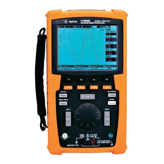
The U1600B Series comprises two models: U1602B and U1604B, with 20 MHz and 40 MHz bandwidths, respectively. With its 4.5- inch LCD color display, it is capable of clearly distinguishing waveforms from two channels. -
Page 34: To Inspect Package Contents
Verify that you have received the following items for the standard shipped components or optional accessories you may have ordered: • U1602B or U1604B handheld digital oscilloscope • Power cord • AC adapter • Oscilloscope probes •... -
Page 35: Standard Shipped Components
Agilent Technologies Sales Office. • If the shipping container is damaged, or the cushioning material shows signs of stress, notify the carrier and the Agilent Technologies Sales Office. Keep the shipping material for the carrier’s inspection. The Agilent Technologies Sales Office would arrange for repair or replacement at Agilent’s discretion without waiting for claim settlement. -
Page 36: Optional Accessories
The power cord type shown in Figure 1-1 is for illustration purposes only. The power cord N O T E type you receive as part of the standard shipping components varies with your region as stated in Table 1-1. Agilent U1602B/U1604B User’s and Service Guide... -
Page 37: To Charge A Battery
Before using the instrument for the first time, fully charge the battery for approximately 25 hours with the unit turned on by using the designated Agilent AC adapter. Ensure that you have the correct line power cord (refer to Table 1- 1). The AC adapter automatically converts input line voltage ranges from 100 VAC –... -
Page 38: Battery Charging
Getting Started Figure 1-3 Battery charging Agilent U1602B/U1604B User’s and Service Guide... -
Page 39: To Power On Instrument
Display Vector on, 50% contrast, graticule grid, persistence off Acquire Normal mode, Run/Stop to Run, cursors and measurement off DMM Voltmeter set to DC, relative off, auto- measurement Ohmmeter set to Resistance, relative off, auto- measurement Agilent U1602B/U1604B User’s and Service Guide... -
Page 40: Factory Setup
Temperature meter set to °C, relative off Ampere meter set to DC, relative off Humidity meter set to %RH, relative off Pressure meter set to psi, relative off. Logger Logger Volt, DC input, Maximum logging Figure 1-4 Factory setup Agilent U1602B/U1604B User’s and Service Guide... -
Page 41: To Perform Self-Calibration
Disconnect all probe and meter connections to the input terminal of the instrument. WA R N I N G Allow the instrument to warm up at least 30 minutes before performing self-calibration. Refer to “Self-Calibration 150” for more information. Agilent U1602B/U1604B User’s and Service Guide... -
Page 42: To Set Date And Time
F4 softkey to enter Utility mode. 2 On page 2/4 of Utility mode, press F1 to select time format in MM/DD/YY or YY/MM/DD. • MM — month • DD — day • YY — year Agilent U1602B/U1604B User’s and Service Guide... -
Page 43: Select The Date Format
3 Press F2 to select Year, Month, Day, Hour, Minute or Second and turn the rotary switch to select the desired value. 4 Press the rotary switch to store the preferences. Figure 1-7 Date and time setting Agilent U1602B/U1604B User’s and Service Guide... -
Page 44: To Set Auto-Power Off
F4 softkey to enter Utility mode. 2 On 1/4 page of Utility mode, press F1 to select your preferred timing: 5 min/10 min/30 min/1 hour/2 hours/4 hours. Figure 1-8 Auto-power off function Agilent U1602B/U1604B User’s and Service Guide... -
Page 45: To Select Quick Help Language
C A U T I O N firmware downloading process. If this is violated, the instrument will hang and may not be able to power off. When this incident occurred, disconnect the battery and repeat step 1 to 10. Agilent U1602B/U1604B User’s and Service Guide... -
Page 46: To Adjust Contrast Of Display
3 To increase the contrast of the display, turn the rotary switch clockwise. To decrease the contrast, turn the rotary switch counter- clockwise. 4 Press F2 again to lock the contrast setting. Figure 1-9 Adjust display contrast Agilent U1602B/U1604B User’s and Service Guide... -
Page 47: To Compensate Scope Probe
4 Connect the passive probe to channel 2 and probe contact to channel 1. The input signal is 3 Vp- p with 1 kHz from channel 1. Figure 1-10 Connection for scope probe compensation Agilent U1602B/U1604B User’s and Service Guide... -
Page 48: Figure 1-11. A 10X Scope Probe With Over Compensation, Adjust The
Figure 1-12 Trimmer capacitor for probe compensation Use a nonmetallic tool to adjust the trimmer capacitor on the probe for the flattest pulse possible, refer to Figure 1- 13. The trimmer capacitor is located as shown in Figure 1- 12. Agilent U1602B/U1604B User’s and Service Guide... - Page 49 Getting Started Proper compensated Over compensated Under compensated Figure 1-13 Pulse shape reference for scope probe compensation Agilent U1602B/U1604B User’s and Service Guide...
- Page 50 Getting Started Agilent U1602B/U1604B User’s and Service Guide...
-
Page 51: Front Panel And Displays Overview
Agilent U1602B/U1604B Handheld Digital Oscilloscope User’s and Service Guide Front Panel and Displays Overview Front Panel Overview Oscilloscope Display Overview Multimeter Display Overview Agilent Technologies... -
Page 52: Front Panel And Displays Overview
Front Panel and Displays Overview Front Panel Overview This chapter describes the front panel controls of the Agilent U1600B series handheld digital oscilloscope series. The front panel keys are used for setting up and making scope and meter measurements. They provide access to the softkey menus for respective function and value setting selected by turning the rotary switch. - Page 53 USB 2.0 host DC input Figure 2-1 U1600B series handheld digital oscilloscope front and side view To EXIT the sub-menu of the main function, press any of the main function keys. N O T E Agilent U1602B/U1604B User’s and Service Guide...
- Page 54 • Acquire mode lets you set the signal acquisition to Normal, Average or Peak modes. • Math mode provides the Dual Waveform Math functions to multiply and subtract waveforms. FFT (Fast Fourier Transform) function is available for U1604B. Agilent U1602B/U1604B User’s and Service Guide...
- Page 55 13 Range By pressing the Autoscale key in any auto- range meter mode, the instrument allows you to select the range of your preference. Agilent U1602B/U1604B User’s and Service Guide...
- Page 56 17 The Quick Help is a built- in function in the instrument. It provides help for each front panel and softkey. To view the quick help for each function, press button. Turn the rotary switch clockwise to go to the next page. Agilent U1602B/U1604B User’s and Service Guide...
-
Page 57: Oscilloscope Display Overview
4 Power source indicator This indicator will shows the status of the battery from full to empty and indicate the AC connectivity for battery charging. Agilent U1602B/U1604B User’s and Service Guide... - Page 58 8 Real- time display You can set the date and time in the User - > Utility mode. 9 Menu display area The softkey below the LCD display allows you to select and set up parameters for the respective mode and menu. Agilent U1602B/U1604B User’s and Service Guide...
-
Page 59: Multimeter Display Overview
4 Real- time display You can set the date and time in the User - > Utility mode. 5 Menu display area The softkey below the LCD display allows you to select and set up parameters for the respective mode and menu. Agilent U1602B/U1604B User’s and Service Guide... - Page 60 Front Panel and Displays Overview Agilent U1602B/U1604B User’s and Service Guide...
-
Page 61: Using The Scope Functions
Agilent U1602B/U1604B Handheld Digital Oscilloscope User’s and Service Guide Using the Scope Functions Vertical Controls Horizontal Controls Trigger Controls Waveform Controls Display Controls Automatic Measurement Cursor Measurement Controls Math Functions Control Save and Recall Controls Autoscale and Run/Stop Controls Utility Controls... -
Page 62: Vertical Controls
Scope menu. You will see the following scope menu display in Figure 3- 1., which shows both channels disabled. Figure 3-1 Scope menu display with displayed of both channels display. Agilent U1602B/U1604B User’s and Service Guide... - Page 63 (refer to the next section for detailed explanation). 6 You can perform the same procedure for channel 2 or for both channels. Agilent U1602B/U1604B User’s and Service Guide...
-
Page 64: Vertical System Setup
3 Notice that the waveform and the ground reference symbol moves vertically with respect to the rotary switch position. The maximum positive reference offset is 250 mV and the minimum negative reference N O T E offset is –250 mV. Agilent U1602B/U1604B User’s and Service Guide... -
Page 65: To Center The Waveform On The Display
Figure 3-4 Reset vertical ground reference symbol to zero volt. Position to 0 is a convenient function to return the waveform offset to the original state N O T E after changing ground offset via rotary switch. Agilent U1602B/U1604B User’s and Service Guide... -
Page 66: To Change Vertical Sensitivity
23”) as shown in Figure 3- 5. Vertical sensitivity Figure 3-5 Vertical sensitivity display By pressing the button for channel 1 or channel 2, the respective channel’s setting N O T E menu will appear. Agilent U1602B/U1604B User’s and Service Guide... -
Page 67: Channel Coupling Control
In this case, only AC component of the input signal can be viewed. The symbol is shown at the top left of the status line. See Figure 3- 6 for AC channel coupling. Figure 3-6 AC channel coupling Agilent U1602B/U1604B User’s and Service Guide... -
Page 68: Dc Channel Coupling
In GND coupling mode, the waveform is disconnected from the oscilloscope input. The symbol is shown at the top left of the status line.See Figure 3- 8 for Gnd channel coupling. Figure 3-8 Gnd channel coupling Agilent U1602B/U1604B User’s and Service Guide... -
Page 69: Probe Attenuation Control
F1 softkey. A pull- up menu is displayed with the selection of 1X, 10X and 100X. 3 Set probe attenuation scale in accordance with the probe you use. Figure 3-9 Probe attenuation scale setting Agilent U1602B/U1604B User’s and Service Guide... -
Page 70: Invert Control
2 On page 2/2 of each respective channel’s submenu, you can turn the Invert control on or off by pressing F2 softkey. See the subsequence three figures for detailed explanation. Figure 3-10 The waveform before inversion. Agilent U1602B/U1604B User’s and Service Guide... - Page 71 The Invert function does not affect triggering. If the instrument is set to trigger on a rising N O T E edge, it remains set to trigger on the same edge and at the same point on the waveform after the channel is inverted. Agilent U1602B/U1604B User’s and Service Guide...
-
Page 72: Horizontal Controls
(with ns indicator) to scale down the time scale factor. The time/div is displayed in status line (refer to “Oscilloscope Display Overview 23”) as shown in Figure 3- 12. Time/division display Figure 3-12 Time/div display in status line Agilent U1602B/U1604B User’s and Service Guide... -
Page 73: To Set Delay Of The Waveforms
4 While turning the rotary switch, you will notice the corresponding time value is displayed under the Time header column. Adjust time base of the displayed waveform Figure 3-13 Changing time base of a waveform Agilent U1602B/U1604B User’s and Service Guide... -
Page 74: To Change Trigger Point Indicator
The amount of delay range (pre- trigger and post- trigger information) is available depending on the sweep speed selected and memory depth. Agilent U1602B/U1604B User’s and Service Guide... -
Page 75: Horizontal Mode Functions
Channel 1 amplitude is plotted on the horizontal X- axis and channel 2 amplitude is plotted on the vertical Y- axis. The time base is turned off. Use the cursors to make measurements on XY mode waveforms. Agilent U1602B/U1604B User’s and Service Guide... -
Page 76: Main/Zoom Mode
The Main mode is the normal viewing mode for the instrument. You can use the Main function to return to the view before magnification, where the horizontal scale factor would then return to its original level. Agilent U1602B/U1604B User’s and Service Guide... - Page 77 See the following figures for the waveform zooming function. Figure 3-16 When Window function is turned on, a zoom area selection bar appears at the center of the display. Adjust rotary switch clockwise to expand the zoom area. Agilent U1602B/U1604B User’s and Service Guide...
-
Page 78: Roll Mode
Roll mode. This enables triggering at these slower time bases. The spanning functions are not available for time base setting of 50 ms/div or slower and N O T E 125 ns/div or faster. Agilent U1602B/U1604B User’s and Service Guide... -
Page 79: Trigger Controls
Normal trigger mode. 2 To select Single trigger mode, press and hold the button again. 3 Press and hold the button to return to Auto trigger mode. Normal trigger mode Figure 3-18 Normal trigger mode Agilent U1602B/U1604B User’s and Service Guide... -
Page 80: Auto Trigger Mode
It continues to flow data through the pre- trigger buffer until the auto trigger overrides the searching and forces a trigger. At the end of the trace, the instrument will stop and display the results. Agilent U1602B/U1604B User’s and Service Guide... -
Page 81: Trigger Types
4 The submenu of edge trigger includes: • Source Press F2 on page 1/2 to select channel source for the trigger. The channel you select is shown in the trigger status line at the right of the display. Agilent U1602B/U1604B User’s and Service Guide... - Page 82 The value of the trigger level is displayed under the Level column. • TTL trigger level sets the trigger level to recognize the High/Low condition in a TTL signal automatically. Agilent U1602B/U1604B User’s and Service Guide...
- Page 83 TTL trigger level sets the trigger level to recognize the High/Low condition in a TTL signal automatically. • ECL trigger level sets the trigger level to recognize the High/Low condition in an ETL signal automatically. Agilent U1602B/U1604B User’s and Service Guide...
-
Page 84: Pattern Trigger
The Pattern trigger identifies a trigger condition by looking for a specific pattern. This pattern is a logical gate combination of the channels. Each channel can have a value of high (H) and low (L). Agilent U1602B/U1604B User’s and Service Guide... - Page 85 Press F3 on page 2/3 to select the types of trigger level adjustment for Input 2. • Manual trigger level allows you to change the trigger level by turning the rotary switch. The value of the trigger level is displayed under the Level column. Agilent U1602B/U1604B User’s and Service Guide...
- Page 86 • The “equal” (=) sets the instrument to trigger with equivalent to the time value. • The “not equal” (≠) sets the instrument to trigger with not equivalent to time value. Agilent U1602B/U1604B User’s and Service Guide...
-
Page 87: Video Trigger
• Line Press F3 on page 2/2 to change the line number in the selected field. Turn the rotary switch to select the desired count number from 5 to 263. Agilent U1602B/U1604B User’s and Service Guide... -
Page 88: Waveform Controls
1 Press button at the front panel to access the User menu. 2 Press F2 to access the Acquire submenu. 3 Press F1 to prompt a pull- up menu for the three acquisition modes selection. Agilent U1602B/U1604B User’s and Service Guide... -
Page 89: Normal Acquisition Mode
The higher the number of averages, the slower the response is to change in the waveform N O T E display. Agilent U1602B/U1604B User’s and Service Guide... -
Page 90: Peak Detection Mode
Peak Detection Mode The Peak Detection mode captures the maximum and minimum values of the sampling signal over multiple acquisition. This is useful to verify aliasing of the displayed waveform. Figure 3-21 Peak Detection Mode Agilent U1602B/U1604B User’s and Service Guide... -
Page 91: Display Controls
User menu. 2 Press F1 to access the Display submenu. 3 Press F1 on page 1/2 of the Display submenu to select the display type from a pull- up menu. Figure 3-22 Dots display type Agilent U1602B/U1604B User’s and Service Guide... -
Page 92: Display Contrast
3 Press F2 on page 1/2 of Display submenu to enable the display contrast setting. 4 Turn rotary switch clockwise to reduce brightness of the display and vice- versa. 5 Press F2 again to fix the contrast value. Agilent U1602B/U1604B User’s and Service Guide... -
Page 93: Graticule
3 Press F1 on page 2/2 to enable the infinite persistence function. Turn off the persistence by pressing F1 again. 4 Press F2 (Clear Display) on page 2/2 to clear and erase previous acquisitions and restart the accumulation of acquisitions. Agilent U1602B/U1604B User’s and Service Guide... -
Page 94: Automatic Measurement
• –Duty • Frequency • Period • Rise Time • Fall Time • +Width • –Width Voltage Measurements • Mean • Cycle mean • Amplitude • Base • Maximum • Minimum • Peak- to- peak Agilent U1602B/U1604B User’s and Service Guide... -
Page 95: To Perform Automatic Measurements
4 Press the rotary switch to set the selected automatic measurement type. Measurement results for both channels are displayed at the measurement line concurrently. 5 Repeat the same steps to select measurements for the other three measurement files. Agilent U1602B/U1604B User’s and Service Guide... -
Page 96: Time Automatic Measurements
+Width x 100 +Duty cycle = Period –Duty The negative duty cycle of a repetitive pulse train is the ratio of the negative pulse width to the period, expressed in percentage. Agilent U1602B/U1604B User’s and Service Guide... -
Page 97: Width
Frequency is defined as 1/period and it used to measure the frequency of a waveform. Rise Time The rise time of a signal is the time difference between the crossing of the lower threshold and the crossing of the upper threshold for a positive- going edge. Agilent U1602B/U1604B User’s and Service Guide... -
Page 98: Fall Time
Mean Cycle The mean cycle value of a measurement is the statistical average of the measurement within a cycle period. Amplitude Amplitude is defined as the difference between the measurement’s Top and Base values. Agilent U1602B/U1604B User’s and Service Guide... -
Page 99: Base
RMS (DC) is the root- mean- square value of the waveform over one or more full periods. If less than one period is displayed, RMS (DC) average is calculated over the full width of the display. Agilent U1602B/U1604B User’s and Service Guide... -
Page 100: Phase And Delay
Phase is the calculated phase shift from input source 1 to input source 2, expressed in degrees. Negative phase shift values indicate that the rising edge of source 1 occur after the rising edge of source 2. Delay x 360 Phase = Source 1 period Agilent U1602B/U1604B User’s and Service Guide... -
Page 101: Delay
1 occur after the selected edge of source 2. Figure 3-29 Delay measurement Preshoot and Overshoot Preshoot Preshoot is the distortion that precedes a major edge transition expressed as a percentage of amplitude (refer to Figure 3- 26). Agilent U1602B/U1604B User’s and Service Guide... -
Page 102: Overshoot
Rising edge overshoot= Amplitude –Overshoot Overshoot is the distortion that follows a major edge transition expressed as a percentage of amplitude (refer to Figure 3- 26). VBase Vmin x 100 – Falling edge overshoot= Amplitude Agilent U1602B/U1604B User’s and Service Guide... -
Page 103: Cursor Measurement Controls
2 Press F1 to enable and select cursor measurement type for X or Y cursor. 3 To turn off this function, press F1. Figure 3-30 Cursor measurement menu Agilent U1602B/U1604B User’s and Service Guide... -
Page 104: X-Cursor Measurement
The X1 measurement is +16.00 mV at +500.0 µs. The X2 measurement is –8.000 mV at –1.000 ms. The delta of X1 and X2 voltage measurement is +24.00 mV with time relative difference of +1.500 ms. Agilent U1602B/U1604B User’s and Service Guide... - Page 105 The X1 measurement is +11.20 mV at +500.0 µs. The X2 measurement is –11.20 mV at –1.000 ms. The delta of X1 and X2 voltage measurement is +22.40 mV with time relative difference of +1.500 ms. Agilent U1602B/U1604B User’s and Service Guide...
- Page 106 X1 cursor line X2 cursor line Figure 3-32 X-cursor measurement for channel 2 signal with X1 and X2 cursor lines 6 In Figure 3- 32, math function is selected. Figure 3-33 Math functions for X-cursor measurement Agilent U1602B/U1604B User’s and Service Guide...
-
Page 107: Y-Cursor Measurement
4 In Figure 3- 33, two cursor lines — Y1 and Y2 mode — are selected, the measurement is made for the signal at channel 1. The Y1 measurement is –154.00 mV. The Y2 measurement is +22.00 mV. The delta of Y1 and Y2 voltage measurement is +176.00 mV. Agilent U1602B/U1604B User’s and Service Guide... - Page 108 5 In Figure 3- 34, the measurement is made for the signal at channel 2. The Y1 measurement is –13.60 mV The Y2 measurement is +56.80 mV. The delta of Y1 and Y2 voltage measurement is +70.40 mV. Agilent U1602B/U1604B User’s and Service Guide...
- Page 109 Figure 3-35 Y-cursor measurement for channel 2 signal with X1 and X2 cursor lines 6 In Figure 3- 35, math function is selected and the result is displayed in red at the top right of the waveform display area. Figure 3-36 Math function for Y-cursor measurement Agilent U1602B/U1604B User’s and Service Guide...
-
Page 110: Math Functions Control
4 To turn off the math function, select “off” with F1 to erase all math data. 5 After selecting the DWM, the submenu of the DWM function prompts the selection of addition and subtraction functions in F2. • CH1 + CH2 • CH1 – • CH2 – Agilent U1602B/U1604B User’s and Service Guide... -
Page 111: Add (Ch1 + Ch2)
Figure 3-37 Addition of channel 1 and channel 2 function Agilent U1602B/U1604B User’s and Service Guide... -
Page 112: Subtraction (Ch1 - Ch2, Ch2 - Ch1)
If the waveforms from channel 1 and channel 2 have different vertical scale factor, the math N O T E waveform vertical scale is automatically set to the higher sensitivity of the vertical scale factor. Figure 3-38 Subtraction signal at channel 2 from channel 1 Agilent U1602B/U1604B User’s and Service Guide... -
Page 113: Fft (Fast Fourier Transform)
Press F2 to select the source (channel 1 or channel 2) for the FFT. V Axis Press F3 to select vertical scale factor expressed in dB/div. There are four scale factors for your selection: • 1 dB • 2 dB Agilent U1602B/U1604B User’s and Service Guide... -
Page 114: Window
To reduce the DC component that potentially affects the FFT waveform magnitude values, N O T E choose AC coupling on the source waveform. Agilent U1602B/U1604B User’s and Service Guide... -
Page 115: Save And Recall Controls
• A waveform saved in a USB flash memory device can be transferred to a PC in either the .bmp or .svw file format. You can convert the waveform from the .svw format to the .csv format using the U1602B/U1604B PC Link application which can be obtained from http://www.agilent.com. Agilent U1602B/U1604B User’s and Service Guide... -
Page 116: Save And Recall Controls Without Usb Flash Memory Device
5 Press the F1 again to load the Setup 1 from the internal memory, refer to Figure 3- 40. 6 Go through the same save and recall setup steps for saving and recalling the subsequent setups. Agilent U1602B/U1604B User’s and Service Guide... - Page 117 Using the Scope Functions Figure 3-40 The <Save> display indicates no setup file is being saved. You can press F1 to save the setup into Setup 1. Agilent U1602B/U1604B User’s and Service Guide...
-
Page 118: To Save And Recall Waveform
5 Press F1 again to load the Waveform 1 from the internal memory. Refer to Figure 3- 42. 6 Go through the same save and recall waveform steps for saving and recalling the subsequent waveforms. Agilent U1602B/U1604B User’s and Service Guide... - Page 119 Figure 3-43 The <Load> display indicates the a waveform file is saved into Waveform 1 and you can press F1 to retrieve the waveform from internal memory. This function is useful for waveform comparison. Agilent U1602B/U1604B User’s and Service Guide...
-
Page 120: To Erase Setup
4 In Figure 3- 44, press F1 to erase the configuration setup from Setup 1. Figure 3-44 The <None> display indicates that no setup file is saved. The <Erase> in Set- up 1 shows that you can erase the setup file from the internal memory. Agilent U1602B/U1604B User’s and Service Guide... -
Page 121: To Erase Waveform
45, press F1 to erase the waveform from Waveform 1. Figure 3-45 The <None> display indicates that no waveform is being saved. The <Erase> in Waveform 1 shows that you can erase the waveform from the internal mem- ory. Agilent U1602B/U1604B User’s and Service Guide... -
Page 122: To Restore Factory Setup
3 On page 1/4 of Save/Load submenu, press F1 to restore the factory default setup. 4 The instrument prompts a “Recall OK?” message to request confirmation on restoring the factory setup. Press F1 to confirm. Agilent U1602B/U1604B User’s and Service Guide... - Page 123 Using the Scope Functions Figure 3-46 Restore factory setup in Save/Load Setup menu. Figure 3-47 The instrument requests confirmation to restore factory default setting. Agilent U1602B/U1604B User’s and Service Guide...
-
Page 124: Save And Recall Controls With Usb Flash Memory Device
4 Plug in USB flash memory, press and hold the button to enter Save/Recall menu. USB flash memory host Figure 3-48 Connect a USB flash memory to save or download waveforms to/from the ex- ternal memory device. Agilent U1602B/U1604B User’s and Service Guide... -
Page 125: To Save Waveform
1 Connect a USB flash memory device. Press and hold to access Save/Recall menu. 2 The display lists the flash memory’s contents. Turn the rotary switch to move the cursor to select the file. Agilent U1602B/U1604B User’s and Service Guide... -
Page 126: To Erase Waveform
2 The display lists the flash memory’s contents. Turn the rotary switch to move the cursor to select the file. 3 Press F3 to erase the file from the list. This step removes the waveform permanently. Agilent U1602B/U1604B User’s and Service Guide... -
Page 127: To Clear Waveform
To Clear Waveform To clear the current displayed waveform from the screen, follow the instructions below: 1 Press and hold to access Save/Recall menu. 2 Press F4 to clear the waveform from the display. Agilent U1602B/U1604B User’s and Service Guide... -
Page 128: Autoscale And Run/Stop Controls
CH1 Invert CH 1 Position 0 div CH 2 Coupling CH 2 Invert CH 2 Position 0 div Time Position Center Trigger Type Edge Trigger Edge CH 1 Trigger Edge Coupling Trigger Edge Slope Rising Agilent U1602B/U1604B User’s and Service Guide... -
Page 129: Run/Stop Controls
In Stop mode, the instrument is forced to stop acquiring signal. The acquisition status is displayed at the right of the display indicating if the instrument is in run or stop mode. Run and Stop acquisition status Figure 3-50 Run and Stop modes Agilent U1602B/U1604B User’s and Service Guide... -
Page 130: Utility Controls
Refer to “To Set Auto- Power Off 12” for the steps to select auto- power off setting. Figure 3-51 Auto-power off control Agilent U1602B/U1604B User’s and Service Guide... -
Page 131: Language Selection
150” on more detailed information of self- calibration. Disconnect all probe connections to the input terminal of the instrument. Allow the WA R N I N G instrument to warm up at least 30 minutes before performing self-calibration. Agilent U1602B/U1604B User’s and Service Guide... -
Page 132: Probe Calibration
If the instrument is under low battery mode in power off condition, when users turn the instrument on, it automatically shuts off after one minute to protect the internal circuit. Figure 3-52 Message display during low battery condition Agilent U1602B/U1604B User’s and Service Guide... -
Page 133: Mute Function
2 On page 4/4 of the Utility menu, press F1 to display the mute on/off menu. 3 Select Mute On to turn off the key sound and low battery alarm alert and vice- versa. Agilent U1602B/U1604B User’s and Service Guide... - Page 134 Using the Scope Functions Agilent U1602B/U1604B User’s and Service Guide...
- Page 135 Agilent U1602B/U1604B Handheld Digital Oscilloscope User’s and Service Guide Using the Digital Multimeter Functions Voltmeter Ohmmeter Auxiliary Meter Relative Function Automatic Measurement in Multimeter Mode Restart Test Auto-range Mode The U1600B series handheld digital oscilloscope is equipped with multimeter functions. The built- in 6000 count resolution true RMS digital multimeter comes with auto- range function that provides flexibility in performing quick and accurate meter measurement.
-
Page 136: Using The Digital Multimeter Functions
5 Probe the test point of the circuit under test. 6 Read the voltage reading from the display. The display indicates the proper decimal point, value and symbols. 7 To perform relative function, refer to “Relative Function 112” section in this chapter. Agilent U1602B/U1604B User’s and Service Guide... - Page 137 Do not switch on or off a motor under test when measuring AC or DC voltage. This is to C A U T I O N avoid the instrument from being damaged due to large voltage surge during the on and off operation. Agilent U1602B/U1604B User’s and Service Guide...
-
Page 138: Ohmmeter
5 Probe the test point of the circuit or device under test. 6 Read the resistance reading from the display. The display indicates the proper decimal point, value and symbols. 7 To perform relative function, please refer to “Relative Function 112” section in this chapter. Agilent U1602B/U1604B User’s and Service Guide... - Page 139 If the device under test is an assembled part of a circuit, it is highly recommended that you N O T E disconnect one site of the device to reduce interference to the resistance reading. Figure 4-3 Resistance measurement Agilent U1602B/U1604B User’s and Service Guide...
-
Page 140: Continuity Test
7 If the resistance is less than 60 W, the audible beeper will sound. 8 Press F3 to perform automatic measurement for minimum, maximum and average readings. 9 Press F4 to refresh and recollect measurement reading. Figure 4-4 Continuity test shorted with audible beeper sound. Agilent U1602B/U1604B User’s and Service Guide... -
Page 141: Diode Test
• Diode is considered open if the instrument displays “OL” in both forward and reverse bias modes. The typical diode forward bias is in the range of 0.3 V to 1.00 V. N O T E Agilent U1602B/U1604B User’s and Service Guide... - Page 142 Using the Digital Multimeter Functions Figure 4-5 Diode in forward bias condition A caution symbol appears in open loop condition Figure 4-6 Diode in open condition Agilent U1602B/U1604B User’s and Service Guide...
-
Page 143: Capacitance Measurement
(cathode). 6 Read the capacitance reading from the display. 7 To perform relative function, please refer to “Relative Function 112” section in this chapter. Figure 4-7 Capacitance measurement Agilent U1602B/U1604B User’s and Service Guide... -
Page 144: Auxiliary Meter
°C or °F respectively. 8 To perform relative function, refer to “Relative Function 112” section in this chapter. 9 Press F3 to perform automatic measurement for minimum, maximum and average readings. Agilent U1602B/U1604B User’s and Service Guide... - Page 145 N O T E Ensure the probe tip surface is dry and clean for good temperature transfer from object to probe tip. Figure 4-8 Temperature measurement in degrees Celsius (°C) together with degree Fahr- enheit (°F) display. Agilent U1602B/U1604B User’s and Service Guide...
-
Page 146: Ampere Meter
12 Press F3 to perform automatic measurement for minimum, maximum and average readings. 13 Press F2 in page 2/2 of the ampere meter submenu to refresh and recollect measurement reading. Agilent U1602B/U1604B User’s and Service Guide... -
Page 147: Humidity Meter
6 Read the humidity reading in %RH from the display. The display indicates the proper decimal point, value and symbols. 7 To perform relative function, please refer to “Relative Function 112” section in this chapter. Agilent U1602B/U1604B User’s and Service Guide... -
Page 148: Pressure Meter
(–) to COM input jacks of the instrument. 6 Touch the material under test with the probe tip. 7 Read the pressure reading from the display. The display indicates the proper decimal point, value and symbols. Agilent U1602B/U1604B User’s and Service Guide... - Page 149 9 Press F3 to perform automatic measurement for minimum, maximum and average readings. 10 Press F4 to refresh and recollect measurement reading. Figure 4-11 Pressure measurement 1 kPa = 6.89476 psi N O T E Agilent U1602B/U1604B User’s and Service Guide...
-
Page 150: Relative Function
1.766 kW (measured value), the delta of approximately 0.586 kW (relative value) will be displayed. Formula is shown as below: Relative value = Measured value - Reference value Figure 4-12 Set the reading as reference value Agilent U1602B/U1604B User’s and Service Guide... - Page 151 Using the Digital Multimeter Functions Figure 4-13 Set the reading as measured value Figure 4-14 Relative value obtained from the delta of the measured and reference value. Agilent U1602B/U1604B User’s and Service Guide...
-
Page 152: Automatic Measurement In Multimeter Mode
The average value is the arithmetic average value of the last 8 readings. To enable the function, press F3 in each respective multimeter function submenu. Refer to Figure 4- 15. Figure 4-15 Automatic measurement in resistance measurement mode Agilent U1602B/U1604B User’s and Service Guide... -
Page 153: Restart Test
2 Notice the range shown below the bar graph changes with every press of the button. 3 Select your preferred range and perform your measurement. 4 To disable the manual range mode, press and hold until the beeper sounds. Agilent U1602B/U1604B User’s and Service Guide... - Page 154 Using the Digital Multimeter Functions Auto-range indication Figure 4-16 Auto-range mode Select the preferred range manually Figure 4-17 Manual range mode Agilent U1602B/U1604B User’s and Service Guide...
-
Page 155: Using The Data Logger Functions
Agilent U1602B/U1604B Handheld Digital Oscilloscope User’s and Service Guide Using the Data Logger Functions Data Logger Function Automatic Measurement in Data Logger Mode CSV Saving Function and Interval Setting Restart Test The U1600B series handheld digital oscilloscope is equipped with data logging function for multimeter measurements. -
Page 156: Data Logger Function
• Voltmeter (displayed as “Volt”) • Ohmmeter (displayed as “Ohm”) • Auxiliary meter (displayed as “Aux”) 3 After selecting the multimeter function, press F2 to select the sub- function of each multimeter function, listed as below: Agilent U1602B/U1604B User’s and Service Guide... - Page 157 • Temperature °C (displayed as “°C Temp”) • Temperature °F (displayed as “°F Temp”) • Relative Humidity (displayed as “%RH”) • Pressure (displayed as “psi”) All multimeter measurements for data logger operates in auto-range mode. N O T E Agilent U1602B/U1604B User’s and Service Guide...
- Page 158 Figure 5-1 Maximum measurement is selected for DC voltage data recording. The initial time base is 15 seconds 150 seconds. — Figure 5-2 After exceeding 150 seconds, the graph automatically compresses to half screen and the time base changes to 30 seconds 300 seconds. — Agilent U1602B/U1604B User’s and Service Guide...
-
Page 159: Automatic Measurement In Data Logger Mode
4 To change the interval settings, press F3 repetitively to scroll down the list and make the selection (refer to Figure 5- 4 below). Figure 5-3 Enabling the CSV saving function Agilent U1602B/U1604B User’s and Service Guide... -
Page 160: Restart Test
Users are able to clear the previously captured readings and refresh the minimum, maximum and average values. To enable this function, press F4 to proceed to page 2/2 of the data logger mode. Then press F1 in page 2/2 to activate the function. Agilent U1602B/U1604B User’s and Service Guide... - Page 161 Agilent U1602B/U1604B Handheld Digital Oscilloscope User’s and Service Guide Service and Maintenance Warranty Services Cleaning Basic Troubleshooting Hints Agilent Technologies...
-
Page 162: Service And Maintenance
Service and Maintenance Warranty Services Standard Warranty (Worldwide) If your instrument fails during the three years warranty period, Agilent Technologies will repair or replace the unit under the terms of your warranty. After the expiration of the warranty, Agilent will offer repair services at a very competitive price. -
Page 163: Accessories Warranty
Or contact Agilent worldwide through the following Web link: www.agilent.com/find/contactus Accessories Warranty Agilent offers warranty for product's accessories for up to 3 months from the end- user acceptance date. Standard Calibration Service (optional) Agilent offers an optional calibration service contract for a period of 3 years from end- user acceptance date. -
Page 164: Returning Instrument To Agilent Technologies For Service
You are recommended to use the original shipping material or order materials from an Agilent Technologies Sales Office. If both options are not available, place 8 to 10 cm (3 to 4 inches) of shock- absorbing and static- free packaging material around the instrument to avoid movement during shipping. -
Page 165: Cleaning
Check the power switch at the front panel is on. ✔ Check the battery condition. Charge the battery if the battery is exhausted. ✔ Contact Agilent Technologies Service Center to obtain technical assistance, if necessary. Agilent U1602B/U1604B User’s and Service Guide... - Page 166 Clear Display to remove the display. ✔ Press the Autoscale button to allow the instrument to automatically trigger the signal to the best display. ✔ Contact the Agilent Technologies Service Center to obtain technical assistance, if necessary. Agilent U1602B/U1604B User’s and Service Guide...
- Page 167 ✔ Contact Agilent Technologies Service Center to obtain technical assistance, if necessary. If you cannot get any response from the instrument, contact the nearest Agilent N O T E Technologies Service Center to obtain further assistance. Agilent U1602B/U1604B User’s and Service Guide...
- Page 168 Service and Maintenance Agilent U1602B/U1604B User’s and Service Guide...
- Page 169 Service and Maintenance Agilent U1602B/U1604B User’s and Service Guide...
-
Page 170: Performance Tests
Agilent U1602B/U1604B Handheld Digital Oscilloscope User’s and Service Guide Performance Tests List of Test Equipment Oscilloscope Performance Verification Tests Multimeter Performance Verification Tests Self-Calibration Self-Calibration Error Code This section documents procedures of performance testing. You will be guided on how to verify instrument operations and perform tests to ensure that the instrument meets the performance specifications. -
Page 171: Performance Test Interval
30 minutes, and perform Self- Calibration before testing. Refer to ““Self- Calibration”” for more information on Self- Calibration. If performance test fails after the Self-Cal, send the instrument to your nearest Agilent N O T E Technologies Service Center for servicing. -
Page 172: List Of Test Equipment
Outputs differ < 0.15 dB Agilent 11667B Cable BNC, quantity of 3 Agilent 10503A Adapter N (m) to BNC (f), quantity of 3 Agilent 1250-0780 Feedthrough 50&, BNC connector (m) and (f), Agilent 11048C quantity of 2 Agilent U1602B/U1604B User’s and Service Guide... -
Page 173: List Of Test Equipment For Multimeter Performance
Table 7-2 List of test equipment for multimeter performance test Application Recommended Equipment DC Voltage FLUKE 5520A AC Voltage FLUKE 5520A Resistance FLUKE 5520A Capacitance FLUKE 5520A Diode Test FLUKE 5520A Continuity FLUKE 5520A Agilent U1602B/U1604B User’s and Service Guide... -
Page 174: Oscilloscope Performance Verification Tests
• Set the Volts/div to the value stated in the first line in Table 7- 3. * Dual Y-Cursor Measurement instructions can be found on page † Full scale on all ranges is defined as 8 divisions multiplied by the V/div setting. Agilent U1602B/U1604B User’s and Service Guide... -
Page 175: Settings Used To Verify Voltage Measurement
2 Place the calibrator in Standby (STBY) mode. 3 Use the BNC tee and cables to connect the calibrator/power supply to the instrument and multimeter as shown in Figure 7- 1. Agilent U1602B/U1604B User’s and Service Guide... - Page 176 Volts/div setting values in Table 7- 3. 9 When you have finished checking all of the power supply setting values, disconnect the power supply from the oscilloscope. 10 Repeat the same verification procedures for channel 2. Agilent U1602B/U1604B User’s and Service Guide...
-
Page 177: Bandwidth Verification Test
8 (Avg 8). Press the rotary switch to set the setting. 3 Set the calibrator to "Level Sine" and OPR/STBY to "OPR". Set the calibrator to 1 MHz and six divisions of amplitude. Agilent U1602B/U1604B User’s and Service Guide... -
Page 178: Signal Generator Frequency Setting
13 The result from step 12 should be greater than or equal to –3.0 dB. 14 Move cable from channel 1 to channel 2 input and repeat the same verification procedures for channel 2. Agilent U1602B/U1604B User’s and Service Guide... -
Page 179: Horizontal Dt And 1/Dt Accuracy Verification Test
Adjust the trigger level to obtain a stable display. 6 Measure the following: • Frequency of 1 MHz — Test limits are 962 kHz to 1.04 MHz. • Period of 1 s — Test limits are 0.96 s to 1.04 Agilent U1602B/U1604B User’s and Service Guide... -
Page 180: Trigger Sensitivity Verification Test
Test limits for the trigger: • 5 MHz at 0.8 div • 20 MHz and 40 MHz at 1 div Refer to Table 7- 1 for the equipment required for this trigger sensitivity verification test. Agilent U1602B/U1604B User’s and Service Guide... - Page 181 3 Verify the trigger sensitivity at maximum bandwidth at 1 division. • Change the output signal of the calibrator to 40 MHz for the U1604B or 20 MHz for the U1602B, and set the amplitude to 100 mVp- p. • Press the autoscale key.
-
Page 182: Multimeter Performance Verification Tests
5 Select each function and range in the order shown in Table 7- 5 and apply the values from the calibrator shown in Table 7- 5 below. 6 Compare measurement results to the corresponding test limits shown in Table 7- 5. Agilent U1602B/U1604B User’s and Service Guide... -
Page 183: Dc Volts Verification Test
6.023 V 30 V 60 V 29.86 V 30.14 V 60 V 60 V 59.77 V 60.23 V 600 V 600 V 597.7 V 602.3 V Figure 7-2 Test connections from calibrator to instrument Agilent U1602B/U1604B User’s and Service Guide... -
Page 184: Ac Voltage Verification Test
58.08 V 61.92 V 300 V 50 Hz 600 V 295.80 V 304.2 V 540 V 1 kHz 600 V 533.40 V 546.60 V 590 V 10 kHz 600 V 571.1 V 608.9 V Agilent U1602B/U1604B User’s and Service Guide... -
Page 185: Resistance Verification Test
60.42 kΩ 600 kΩ 600 kΩ 595.8 kΩ 604.2 kΩ 3 MΩ 6 MΩ 2.973 MΩ 3.027 MΩ 6 MΩ 6 MΩ 5.958 MΩ 6.042 MΩ 60 MΩ 60 MΩ 59.28 MΩ 60.72 MΩ Agilent U1602B/U1604B User’s and Service Guide... -
Page 186: Capacitance Verification Test
613.2 nF 6 mF 6 mF 5.868 mF 6.132 mF 36 mF 60 mF 35.16 mF 36.84 mF 60 mF 60 mF 58.68 mF 61.32 mF 300 mF 300 mF 293.4 mF 306.6 mF Agilent U1602B/U1604B User’s and Service Guide... -
Page 187: Diode Verification Test
6 Compare the measurement results to the corresponding test limits shown in table 7- 9. Table 7-9 Diode Verification Test Calibrator Voltage Function Min Limit Max Limit 0.9 V Diode 0.8812 V 0.9188 V Agilent U1602B/U1604B User’s and Service Guide... -
Page 188: Continuity Verification Test
Figure 7- 2 using banana plug. Ω 5 Apply a resistance output of 30 from the calibrator, buzzer should sound. Ω 6 Apply a resistance output of 75 from the calibrator, buzzer should not sound. Agilent U1602B/U1604B User’s and Service Guide... -
Page 189: Self-Calibration
2 On page 3/4 of Utility mode, press F1 to start self- calibration. A self- calibration dialog box appears to alert user to remove all input connections to the instrument before pressing F1 to start self- calibration. Agilent U1602B/U1604B User’s and Service Guide... -
Page 190: Self-Calibration Error Code
Performance Tests Figure 7-3 Self-calibration dialog box Self-Calibration Error Code The following error codes indicate failures that may occur during the instrument’s self- calibration. Agilent U1602B/U1604B User’s and Service Guide... -
Page 191: Self-Calibration Error Code
• all time base divisions except 125 ns/div • when using both channels at 125 ns/div • OE — Zero offset calibration error N O T E • TE — Trigger level calibration error Agilent U1602B/U1604B User’s and Service Guide... - Page 192 1111 1111 1111 (Hexadecimal code) 3 If multi- error occurred in TE3, TE4, OE2 and OE3, the hexadecimal code “0x600C” will be displayed as self- calibration result. 0000 0110 0000 0000 1100 (Hexadecimal code) Agilent U1602B/U1604B User’s and Service Guide...
- Page 193 Performance Tests Agilent U1602B/U1604B Handheld Digital Oscilloscope Test Record Serial No. Test by Test Interval Work Order No. Recommended Next Testing Temperature Oscilloscope Performance Verification Tests Voltage Measurement Accuracy Volt/div Power Supply Setting Test Limits Channel 1 Channel 2 100 V/div...
- Page 194 Channel 2 100 mVp-p at 5 MHz 0.8 division at 5 MHz [PASS/FAIL] [PASS/FAIL] 100 mVp-p at 20 MHz 1 division at 20 MHz (U1602B) [PASS/FAIL] [PASS/FAIL] 100 mVp-p at 40 MHz 1 division at 40 MHz (U1604B) [PASS/FAIL] [PASS/FAIL]...
- Page 195 Diode Verification Test Calibrator Voltage Test Limit Results 0.9 V 0.8812 V to 0.9188 V Continuity Verification Test Calibrator Settings Condition Results 30 W Buzzer sounds on [PASS/FAIL] 75 W Buzzer sounds off [PASS/FAIL] Agilent U1602B/U1604B User’s and Service Guide...
-
Page 196: General Disassemble
Agilent U1602B/U1604B Handheld Digital Oscilloscope User’s and Service Guide General Disassemble Mechanical Disassemble Replacement Parts This chapter guides you step- by- step on how to dismantle the instrument and install the replacement assembly. To assemble back the instrument, follow the instructions in reverse order. -
Page 197: Mechanical Disassemble
Only service-trained personnel is authorized to perform calibration adjustment to the instrument. Send the instrument to the nearest Agilent Technologies service center for calibration adjustment. Agilent U1602B/U1604B User’s and Service Guide... -
Page 198: To Remove Stand
2 Push and lift up gently at either side of the stand as pointed in Figure 8- 1. Figure 8-1 Push towards the arrow direction to remove the stand 3 Remove the stand from the rear panel of the instrument. Figure 8-2 Disassemble the stand from the instrument Agilent U1602B/U1604B User’s and Service Guide... -
Page 199: To Remove Battery Pack
To remove battery pack without stand installed, perform the instructions below and followed by the battery removing procedures: • To remove stand 1 Remove two screw as pointed in Figure 8- 3. Figure 8-3 Remove battery cover screw Agilent U1602B/U1604B User’s and Service Guide... -
Page 200: To Replace Battery Pack
• Use only insulated probes and leads specified. • Only replace batteries with 7.2 V Ni-MH custom pack For battery replacement purpose, you can remove battery pack without removing stand, follow the steps below: Agilent U1602B/U1604B User’s and Service Guide... - Page 201 2 Use tweezer to unplug the battery pin connector gently through the stand hole as shown in Figure 8- 6. Figure 8-6 Unplug 2-wire connector with a tweezer. 3 Install a new battery pack and proceed to reassemble the battery pack in reverse instructions. Agilent U1602B/U1604B User’s and Service Guide...
- Page 202 For battery replacement, ensure the new battery pack are located in the correct polarity in N O T E the battery compartment and proper contacts between the 3-wire connection to the PCBA board. Assemble the battery pack into the instrument by following the reverse diassemble process. Agilent U1602B/U1604B User’s and Service Guide...
-
Page 203: To Remove Handler
Figure 8- 7 from the plastic cover. Handler Figure 8-7 Remove screw from the rear cover 3 Gently push up the front panel and remove the handler hook from hook clamp. Hook Clamp Figure 8-8 Remove handler from the instrument Agilent U1602B/U1604B User’s and Service Guide... -
Page 204: To Remove Front And Rear Casing
Remove the AC power connector from the instrument and keep safe for the instrument re- assemble. Multimeter input terminal connector AC Power Connector Figure 8-9 Remove and keep the above wear-and-tear parts for re-assemble process Agilent U1602B/U1604B User’s and Service Guide... - Page 205 General Disassemble Figure 8-10 Remove front casing (right) and rear casing (left) from PCBA of the instrument Agilent U1602B/U1604B User’s and Service Guide...
-
Page 206: To Remove Keypad
Figure 8-11 Remove the ten screws from the front cover 3 Disengage the keypad interface board and pull the rubber keypad from the front cover. Figure 8-12 Remove keypad from the front cover Agilent U1602B/U1604B User’s and Service Guide... -
Page 207: To Dismantle System Boards
5 Gently segregate both the PCBA boards from each other. • The first PCBA board with LCD display unit attached is the multimeter measurement board. • The second PCBA board is the scope measurement board. Agilent U1602B/U1604B User’s and Service Guide... -
Page 208: To Remove Lcd Display
2 Unscrew the four screw as located in the Figure 8- 14. Figure 8-14 Remove four screw to dismantle the LCD display unit To re-assemble the instrument, follow the reverse instructions of this chapter. N O T E Agilent U1602B/U1604B User’s and Service Guide... -
Page 209: Replacement Parts
You can order replacement parts from Agilent using the part number as listed in Table 8- 1. To order replacement parts from Agilent, do the following: 1 Contact your nearest Agilent Sales Office or Service Center. -
Page 210: Characteristics And Specifications
Agilent U1602B/U1604B Handheld Digital Oscilloscope User’s and Service Guide Characteristics and Specifications Specifications Characteristics General Characteristics Environmental Conditions Pollution Degree Measurement Category Measurement Category Definitions This chapter lists specifications, characteristics, environmental conditions, and measurement category for Agilent U1602B and U1604B oscilloscope. Agilent Technologies... -
Page 211: Specifications
50 mV/div to 100 V/div: ± 3% full scale Scope Channel Triggering Trigger sensitivity DC to 5 MHz: 0.8 divisions U1602B: 5 MHz to 20 MHz — 1 division U1604B: 5 MHz to 40 MHz — 1 division Agilent U1602B/U1604B User’s and Service Guide... - Page 212 1.000 V 0.5 mA 2.0 + 0.08 [1] For temperature between 0 C to 18 C and 28 C to 50 C , add 0.1% of reading + 0.02% of range for every degree Celsius. Agilent U1602B/U1604B User’s and Service Guide...
- Page 213 600.0 A 50 Hz – 1 kHz 1.0 + 0.2 DC Current 60.00 A 1.0 + 0.08 600.0 A 1.0 + 0.08 Humidity 100.00 % 1.0 + 0.08 Pressure, PSI 600.0 psi 1.0 + 0.08 Agilent U1602B/U1604B User’s and Service Guide...
-
Page 214: Characteristics
AC coupled < 10 Hz without probe < 1 Hz with 10 MW 10:1 passive probe Rise time U1602B: < 17.5 ns U1604B: < 8.8 ns Single shot bandwidth U1602B: 20 MHz U1604B: 40 MHz Agilent U1602B/U1604B User’s and Service Guide... - Page 215 ±0.1 div ±2 mV ±0.5% offset value Single cursor accuracy 4% full scale Dual cursor accuracy 4% full scale Horizontal System Range U1602B: 50 ns to 50 s/div U1604B: 10 ns to 50 s/div Resolution U1602B: 2 ns U1604B: 400 ps Reference position Left, center, right...
- Page 216 ± 0.5 divisions Trigger sensitivity DC to 5 MHz: 0.8 divisions U1602B: 5 MHz to 20 MHz — 1 division U1604B: 5 MHz to 40 MHz — 1 division Coupling DC, AC (< 1 Hz), HF reject (> 50 kHz), LF reject (<30 kHz), Noise reject...
- Page 217 Build-in help system Functional help displayed by pressing help button Real time clock Time and date (user adjustable) Storage Save/Recall (non-volatile) Up to 10 setups and traces [1] FFT function is only available for U1604B model. Agilent U1602B/U1604B User’s and Service Guide...
- Page 218 Data Logger Source Digital multimeter measurements Range 10 divisions Record size 250 points Time span Auto range 150 seconds to 20 days Time reference Time from start Record method Selectable minimum, maximum and average Agilent U1602B/U1604B User’s and Service Guide...
-
Page 219: Sampling Rate
1.25 MSa/s 12.5 Sa/s 50 us 500 kSa/s 5 Sa/s 100 us 250 kSa/s 10 s 2.5 Sa/s 200 us 125 kSa/s 20 s 1.25 Sa/s 500 us 50 kSa/s 50 s 0.5 Sa/s Agilent U1602B/U1604B User’s and Service Guide... -
Page 220: General Characteristics
C to 50 Non-operating: –20 C to 70 Humidity Operating full accuracy to 80% RH at 40 Altitude Operating: Up to 2000 m Non-operating: 15000 m (50000 ft) Shock and Vibration Tested to IEC/EN 60068-2 Agilent U1602B/U1604B User’s and Service Guide... - Page 221 Characteristics and Specifications ESD tolerance ± 4 kV Safety Compliance IEC 61010-1:2001 / EN61010-1:2001 Canada: CSA C22.2 No. 61010-1:2004 USA: UL 61010-1:2004 Pollution degree 2 This instrument is rated for indoor use only. Agilent U1602B/U1604B User’s and Service Guide...
-
Page 222: Environmental Conditions
Occasionally a temporary conductivity caused by condensation may occur. Example is general indoor environment. Pollution Degree 3: Conductive pollution occurs, or dry, non- conductive pollution occurs which becomes conductive due to condensation which is expected. Example is sheltered outdoor environment. Agilent U1602B/U1604B User’s and Service Guide... -
Page 223: Measurement Category
Characteristics and Specifications Measurement Category The U1602B and U1604B oscilloscope is intended to be used for measurement in Measurement Category III, 300 V for scope measurement and Measurement Category III, 300 V and Category II, 600 V for multimeter measurement. - Page 224 Voltage ratings are Vrms (50/60 Hz) for AC sine wave and VDC for DC applications. Maximum floating voltage WA R N I N G • From any terminal to ground 300 Vrms CAT III (up to 400 Hz) — Agilent U1602B/U1604B User’s and Service Guide...
- Page 225 Minimum power 4 Frames multimeter capacitance Frequency Capacitance Verification Test Front panel Channel Selection characteristics Normal acquisition mode cleaning Normal Trigger General Characteristics Compensate Getting Started continuity graticule Continuity Verification Test ohmmeter Grid Contrast Agilent U1602B/U1604B User’s and Service Guide...
- Page 226 Probe Calibration Product reference temperature Pulse Trigger test equipments Test Record Time Quick Help Quick Start Guide Trigger Trigger Modes Trigger point Trigger status Range Troubleshooting Real rear recall Rectangle USB flash memory relative User Agilent U1602B/U1604B User’s and Service Guide...
- Page 227 (fax) (65) 6755 0042 Or visit Agilent worlwide Web at: www.agilent.com/find/assist Product specifications and descriptions in this document are subject to change without notice. Always refer to the Agilent Web site for the latest revision. © Agilent Technologies, Inc. 2006–2013 Printed in Malaysia...