Sign In
Upload
Manuals
Brands
Agilent Technologies Manuals
Test Equipment
InfiniiVision 3000 X-Series
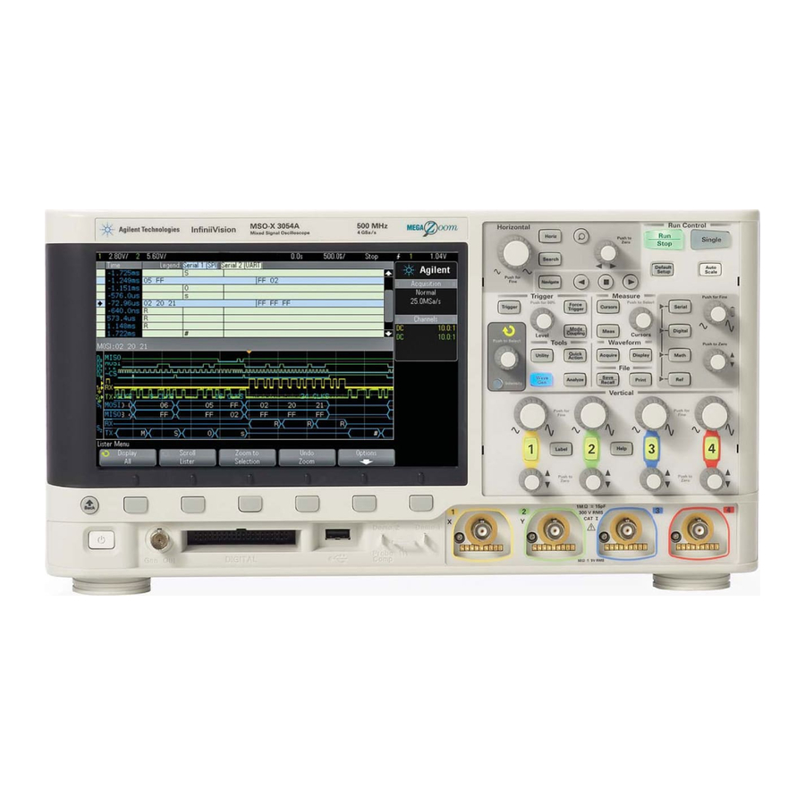
Agilent Technologies InfiniiVision 3000 X-Series Manuals
Manuals and User Guides for Agilent Technologies InfiniiVision 3000 X-Series. We have
7
Agilent Technologies InfiniiVision 3000 X-Series manuals available for free PDF download: Programmer's Manual, User Manual, Service Manual, Datasheet
Agilent Technologies InfiniiVision 3000 X-Series Programmer's Manual (1282 pages)
Oscilloscopes
Brand:
Agilent Technologies
| Category:
Test Equipment
| Size: 7.19 MB
Table of Contents
Table of Contents
7
In this Book
3
Table of Contents
7
General :Search Commands/Search:edge Commands
21
1 What's New
31
What's New in Version 2.30
32
What's New in Version 2.20
33
What's New in Version 2.10
36
What's New in Version 2.00
37
What's New in Version 1.20
41
What's New in Version 1.10
43
Version 1.00 at Introduction
44
Command Differences from 7000B Series Oscilloscopes
45
2 Setting up
49
Step 1. Install Agilent IO Libraries Suite Software
50
Step 2. Connect and Set up the Oscilloscope
51
Using the LAN Interface
51
Using the USB (Device) Interface
51
Using the GPIB Interface
52
Step 3. Verify the Oscilloscope Connection
53
3 Getting Started
59
Basic Oscilloscope Program Structure
60
Capturing Data
60
Initializing
60
Analyzing Captured Data
61
Programming the Oscilloscope
62
Referencing the IO Library
62
Initializing the Interface and the Oscilloscope
63
Opening the Oscilloscope Connection Via the IO Library
63
Using :Autoscale to Automate Oscilloscope Setup
64
Using Other Oscilloscope Setup Commands
64
Capturing Data with the :Digitize Command
65
Reading Query Responses from the Oscilloscope
67
Reading Definite-Length Block Query Response Data
68
Reading Query Results into Numeric Variables
68
Reading Query Results into String Variables
68
Sending Multiple Queries and Reading Results
69
Checking Instrument Status
70
Other Ways of Sending Commands
71
Sending SCPI Commands Using Browser Web Control
71
Telnet Sockets
71
4 Commands Quick Reference
73
Command Summary
74
CLS (Clear Status)
76
ESE (Standard Event Status Enable)
76
ESR (Standard Event Status Register)
76
IDN (Identification Number)
76
LRN (Learn Device Setup)
76
OPC Operation Complete
76
SRE (Service Request Enable)
78
STB (Read Status Byte)
78
TRG Trigger
78
TST (Self Test)
78
WAI (Wait to Continue)
78
6 Root (:) Commands
79
AER (Arm Event Register)
79
Autoscale:channels
79
Autoscale:fdebug
79
Blank
79
Mteenable (Mask Test Event Enable Register)
80
OPEE (Operation Status Enable Register)
80
Pwrenable (Power Event Enable Register)
81
Run
81
Serial
81
Single
81
Stop
81
TER (Trigger Event Register)
82
7 :Acquire Commands
82
Acquire:complete
82
Acquire:count
82
Acquire:mode
82
Acquire:points
82
Channel<N>:Vernier
86
11 :DEMO Commands
86
Demo:function
86
Demo:function:phase:phase
86
Demo:output
86
12 :Digital<D> Commands
87
Digital<D>:Display
87
Digital<D>:Label
87
Digital<D>:Position
87
Digital<D>:Size
87
Digital<D>:Threshold
87
Display:annotation
87
Display:annotation:background
87
Display:annotation:color
87
Display:annotation:text
88
Display:clear
88
Display:data
88
Display:label
88
Display:lablist
88
Display:persistence
88
Display:vectors
88
DVM:arange
88
DVM:current
88
DVM:enable
88
DVM:mode
89
Table of Contents
148
Advertisement
Agilent Technologies InfiniiVision 3000 X-Series Programmer's Manual (1232 pages)
X-Series
Brand:
Agilent Technologies
| Category:
Test Equipment
| Size: 6.92 MB
Table of Contents
In this Book
3
Table of Contents
7
1 What's New
31
What's New in Version 2.10
32
What's New in Version 2.00
33
What's New in Version 1.20
37
What's New in Version 1.10
39
Version 1.00 at Introduction
40
Command Differences from 7000B Series Oscilloscopes
41
2 Setting up
45
Step 1. Install Agilent IO Libraries Suite Software
46
Step 2. Connect and Set up the Oscilloscope
47
Using the USB (Device) Interface
47
Using the LAN Interface
47
Using the GPIB Interface
48
Step 3. Verify the Oscilloscope Connection
49
3 Getting Started
55
Basic Oscilloscope Program Structure
56
Initializing
56
Capturing Data
56
Analyzing Captured Data
57
Programming the Oscilloscope
58
Referencing the IO Library
58
Opening the Oscilloscope Connection Via the IO Library
59
Initializing the Interface and the Oscilloscope
59
Getting Started
59
Using :Autoscale to Automate Oscilloscope Setup
60
Using Other Oscilloscope Setup Commands
60
Capturing Data with the :Digitize Command
61
Reading Query Responses from the Oscilloscope
63
Reading Query Results into String Variables
64
Reading Query Results into Numeric Variables
64
Reading Definite-Length Block Query Response Data
64
Reading Definite- Length Block Query Response Data
64
Sending Multiple Queries and Reading Results
65
Checking Instrument Status
66
Other Ways of Sending Commands
67
Telnet Sockets
67
Sending SCPI Commands Using Browser Web Control
67
4 Commands Quick Reference
69
Command Summary
70
CLS (Clear Status)
72
ESE (Standard Event Status Enable)
72
ESR (Standard Event Status Register)
72
IDN (Identification Number)
72
LRN (Learn Device Setup)
72
OPC Operation Complete
72
SRE (Service Request Enable)
74
STB (Read Status Byte)
74
TRG Trigger
74
TST (Self Test)
74
WAI (Wait to Continue)
74
6 Root (:) Commands
75
Activity
75
AER (Arm Event Register)
75
Autoscale:amode
75
Autoscale:channels
75
Autoscale:fdebug
75
Blank
75
Digitize
76
Mteenable (Mask Test Event Enable Register)
76
OPEE (Operation Status Enable Register)
76
Print
77
Pwrenable (Power Event Enable Register)
77
Run
77
Serial
77
Single
77
Stop
77
7 :Acquire Commands
78
Acquire:complete
78
Acquire:count
78
Acquire:mode
78
Acquire:points
78
Channel<N>:Vernier
81
OPT (Option Identification)
165
RST (Reset)
168
SAV (Save)
171
Print
207
Status
214
Acquire:segmented:analyze
225
Acquire:segmented:count
226
Acquire:segmented:index
227
Acquire:srate
230
Acquire:type
231
Bus<N>:Bit<M
235
Bus<N>:Bits
236
Bus<N>:Clear
238
Bus<N>:Display
239
Bus<N>:Label
240
Bus<N>:Mask
241
Calibrate:date
245
Calibrate:label
246
Calibrate:output
247
Calibrate:protected
248
Calibrate:start
249
Calibrate:status
250
Calibrate:temperature
251
Calibrate:time
252
Channel<N>:Bwlimit
256
Channel<N>:Coupling
257
Channel<N>:Display
258
Channel<N>:Impedance
259
Channel<N>:Invert
260
Channel<N>:Label
261
Channel<N>:Offset
262
Channel<N>:Probe
263
Channel<N>:Probe:head[:Type]
264
Channel<N>:Probe:ID
265
Channel<N>:Probe:skew
266
Channel<N>:Probe:stype
267
Channel<N>:Protection
268
Channel<N>:Range
269
Channel<N>:Scale
270
Channel<N>:Units
271
11 :DEMO Commands
274
Demo:function
274
Demo:function:phase:phase
278
Demo:output
279
Digital<D>:Display
283
Digital<D>:Label
284
Digital<D>:Position
285
Digital<D>:Size
286
Digital<D>:Threshold
287
13 :Display Commands
290
Display:annotation
291
Display:annotation:background
292
Display:annotation:color
293
Display:annotation:text
294
Display:clear
295
Display:data
296
Display:label
297
Display:lablist
298
Display:persistence
299
Display:vectors
300
14 :External Trigger Commands
301
External:bwlimit
302
External:probe
303
External:range
304
External:units
305
15 :Function Commands
307
Function:bus:clock
312
Function:bus:slope
313
Function:bus:yincrement
314
Function:bus:yorigin
315
Function:bus:yunits
316
Function:display
317
Function[:Fft]:Center
318
Function[:Fft]:Span
319
Function[:Fft]:Vtype
320
Function[:Fft]:Window
321
Function:frequency:highpass
322
Function:frequency:lowpass
323
Function:goft:operation
324
Function:goft:source1
325
Function:goft:source2
326
Function:integrate:ioffset
327
Function:linear:gain
328
Function:linear:offset
329
Function:offset
330
Function:operation
331
Function:range
333
Function:reference
334
Function:scale
335
Function:source1
336
Function:source2
338
Function:trend:measurement
339
Hardcopy:area
343
Hardcopy:aprinter
344
Hardcopy:factors
345
Hardcopy:ffeed
346
Hardcopy:inksaver
347
Hardcopy:layout
348
Hardcopy:network:address
349
Hardcopy:network:apply
350
Hardcopy:network:domain
351
Hardcopy:network:password
352
Hardcopy:network:slot
353
Hardcopy:network:username
354
Hardcopy:palette
355
Hardcopy:printer:list
356
Hardcopy:start
357
Lister:data
360
Lister:display
361
Lister:reference
362
Marker:mode
365
Marker:x1Position
366
Marker:x1Y1Source
367
Marker:x2Position
368
Marker:x2Y2Source
369
Marker:xdelta
370
Marker:xunits
371
Marker:xunits:use
372
Marker:y1Position
373
Marker:y2Position
374
Marker:ydelta
375
Marker:yunits
376
Marker:yunits:use
377
Agilent Technologies InfiniiVision 3000 X-Series User Manual (440 pages)
Brand:
Agilent Technologies
| Category:
Test Equipment
| Size: 8.12 MB
Table of Contents
Safety Notices
2
Infiniivision 3000 X-Series Oscilloscopes-At a Glance
3
Table of Contents
6
In this Guide
6
Utility Settings
20
Getting Started
25
Inspect the Package Contents
25
Install the Optional LAN/VGA or GPIB Module
28
Tilt the Oscilloscope for Easy Viewing
28
Power-On the Oscilloscope
29
Connect Probes to the Oscilloscope
30
Maximum Input Voltage at Analog Inputs
30
Do Not Float the Oscilloscope Chassis
31
Input a Waveform
31
Recall the Default Oscilloscope Setup
31
Use Auto Scale
32
Compensate Passive Probes
34
Learn the Front Panel Controls and Connectors
35
Horizontal Controls," Starting on
38
Vertical Controls," Starting on
41
Digital Channels," Starting on
42
Front Panel Overlays for Different Languages
42
Learn the Rear Panel Connectors
44
Learn the Oscilloscope Display
46
Access the Built-In Quick Help
47
Horizontal Controls
50
To Adjust the Horizontal (Time/DIV) Scale
50
To Adjust the Horizontal Delay (Position)
51
Panning and Zooming Single or Stopped Acquisitions
52
To Change the Horizontal Time Mode (Normal, XY, or Roll)
53
XY Time Mode
54
To Display the Zoomed Time Base
56
To Change the Horizontal Scale Knob's Coarse/Fine Adjustment Setting
58
To Position the Time Reference (Left, Center, Right)
58
Searching for Events
59
To Set up Searches
59
Triggers," Starting on
60
To Copy Search Setups
60
Navigating the Time Base
60
To Navigate Time
61
To Navigate Search Events
61
To Navigate Segments
62
Vertical Controls
64
To Turn Waveforms on or off (Channel or Math)
64
To Adjust the Vertical Scale
65
To Adjust the Vertical Position
65
To Specify Channel Coupling
65
To Specify Channel Input Impedance
66
To Specify Bandwidth Limiting
67
To Change the Vertical Scale Knob's Coarse/Fine Adjustment Setting
67
To Invert a Waveform
68
Setting Analog Channel Probe Options
68
To Specify the Channel Units
69
To Specify the Probe Attenuation
69
To Specify the Probe Skew
70
To Calibrate a Probe
70
Math Waveforms
73
To Display Math Waveforms
73
To Perform Transforms or Filters on an Arithmetic Operation
75
To Adjust the Math Waveform Scale and Offset
75
Units for Math Waveforms
76
Math Operators
76
Add or Subtract
77
Multiply or Divide
77
Math Transforms
78
Differentiate
79
Integrate
80
FFT Measurement
83
Square Root
90
Ax + B
90
Square
91
Absolute Value
92
Common Logarithm
92
Natural Logarithm
93
Exponential
93
Base 10 Exponential
94
Math Filters
94
High Pass and Low Pass Filter
95
Math Visualizations
96
Magnify
96
Measurement Trend
97
Chart Logic Bus Timing
98
Chart Logic Bus State
99
Reference Waveforms
101
To Save a Waveform to a Reference Waveform Location
101
To Display a Reference Waveform
102
To Scale and Position Reference Waveforms
103
To Adjust Reference Waveform Skew
103
To Display Reference Waveform Information
104
To Save/Recall Reference Waveform Files To/From a USB Storage Device
104
Digital Channels
105
To Connect the Digital Probes to the Device under Test
105
Probe Cable for Digital Channels
106
Acquiring Waveforms Using the Digital Channels
109
To Display Digital Channels Using Autoscale
109
Interpreting the Digital Waveform Display
110
To Change the Displayed Size of the Digital Channels
111
To Switch a Single Channel on or off
112
To Switch All Digital Channels on or off
112
To Switch Groups of Channels on or off
112
To Change the Logic Threshold for Digital Channels
112
To Reposition a Digital Channel
113
To Display Digital Channels as a Bus
114
Digital Channel Signal Fidelity: Probe Impedance and Grounding
117
Input Impedance
118
Probe Grounding
120
Best Probing Practices
122
To Replace Digital Probe Leads
122
Serial Decode
125
Serial Decode Options
125
Lister
126
Searching Lister Data
128
Display Settings
131
To Adjust Waveform Intensity
131
To Set or Clear Persistence
133
To Clear the Display
134
To Select the Grid Type
134
To Adjust the Grid Intensity
135
To Freeze the Display
135
Labels
137
To Turn the Label Display on or off
137
To Assign a Predefined Label to a Channel
138
To Define a New Label
139
To Load a List of Labels from a Text File You Create
140
To Reset the Label Library to the Factory Default
141
Triggers
143
Adjusting the Trigger Level
145
Forcing a Trigger
145
Edge Trigger
146
Edge then Edge Trigger
148
Pulse Width Trigger
149
Pattern Trigger
152
Hex Bus Pattern Trigger
155
OR Trigger
155
Rise/Fall Time Trigger
157
Nth Edge Burst Trigger
158
Runt Trigger
160
Setup and Hold Trigger
162
Video Trigger
163
To Set up Generic Video Triggers
168
To Trigger on a Specific Line of Video
168
To Trigger on All Sync Pulses
170
To Trigger on a Specific Field of the Video Signal
170
To Trigger on All Fields of the Video Signal
171
To Trigger on Odd or Even Fields
172
USB Trigger
175
Serial Trigger
177
Trigger Mode/Coupling
179
To Select the Auto or Normal Trigger Mode
180
To Select the Trigger Coupling
182
To Enable or Disable Trigger Noise Rejection
183
To Enable or Disable Trigger HF Reject
183
To Set the Trigger Holdoff
184
External Trigger Input
184
Maximum Voltage at Oscilloscope External Trigger Input
185
Acquisition Control
187
Running, Stopping, and Making Single Acquisitions (Run Control)
187
Overview of Sampling
189
Sampling Theory
189
Aliasing
189
Oscilloscope Bandwidth and Sample Rate
190
Oscilloscope Rise Time
191
Oscilloscope Bandwidth Required
192
Memory Depth and Sample Rate
193
Selecting the Acquisition Mode
193
Normal Acquisition Mode
194
Peak Detect Acquisition Mode
194
Averaging Acquisition Mode
197
High Resolution Acquisition Mode
199
Acquiring to Segmented Memory
199
Advertisement
Agilent Technologies InfiniiVision 3000 X-Series User Manual (424 pages)
InfiniiVision 3000 X-Series
Brand:
Agilent Technologies
| Category:
Test Equipment
| Size: 7.71 MB
Table of Contents
Safety Notices
2
Infiniivision 3000 X-Series Oscilloscopes-At a Glance
3
Math Waveforms
4
Table of Contents
5
In this Guide
5
Utility Settings
19
Getting Started
23
Inspect the Package Contents
23
Install the Optional LAN/VGA or GPIB Module
26
Tilt the Oscilloscope for Easy Viewing
26
Power-On the Oscilloscope
27
Connect Probes to the Oscilloscope
28
Maximum Input Voltage at Analog Inputs
28
Do Not Float the Oscilloscope Chassis
29
Input a Waveform
29
Recall the Default Oscilloscope Setup
29
Use Auto Scale
30
Compensate Passive Probes
32
Learn the Front Panel Controls and Connectors
33
Horizontal Controls," Starting on
36
Vertical Controls," Starting on
39
Digital Channels," Starting on
40
Front Panel Overlays for Different Languages
40
Learn the Rear Panel Connectors
42
Learn the Oscilloscope Display
43
Access the Built-In Quick Help
45
Horizontal Controls
48
To Adjust the Horizontal (Time/DIV) Scale
48
To Adjust the Horizontal Delay (Position)
49
Panning and Zooming Single or Stopped Acquisitions
50
To Change the Horizontal Time Mode (Normal, XY, or Roll)
51
XY Time Mode
52
To Display the Zoomed Time Base
54
To Change the Horizontal Scale Knob's Coarse/Fine Adjustment Setting
56
To Position the Time Reference (Left, Center, Right)
56
Searching for Events
57
To Set up Searches
57
Triggers," Starting on
58
To Copy Search Setups
58
Navigating the Time Base
58
To Navigate Time
59
To Navigate Search Events
59
To Navigate Segments
60
Vertical Controls
62
To Turn Waveforms on or off (Channel or Math)
62
To Adjust the Vertical Scale
63
To Adjust the Vertical Position
63
To Specify Channel Coupling
63
To Specify Channel Input Impedance
64
To Specify Bandwidth Limiting
65
To Change the Vertical Scale Knob's Coarse/Fine Adjustment Setting
65
To Invert a Waveform
66
Setting Analog Channel Probe Options
66
To Specify the Channel Units
67
To Specify the Probe Attenuation
67
To Specify the Probe Skew
68
To Calibrate a Probe
68
Math Waveforms
71
To Display Math Waveforms
71
To Perform Transforms or Filters on an Arithmetic Operation
73
To Adjust the Math Waveform Scale and Offset
73
Units for Math Waveforms
74
Math Operators
74
Add or Subtract
75
Multiply or Divide
75
Math Transforms
76
Differentiate
77
Integrate
78
FFT Measurement
81
Square Root
88
Ax + B
88
Square
89
Absolute Value
90
Common Logarithm
90
Natural Logarithm
91
Exponential
91
Base 10 Exponential
92
Math Filters
92
High Pass and Low Pass Filter
93
Math Visualizations
94
Magnify
94
Measurement Trend
95
Chart Logic Bus Timing
96
Chart Logic Bus State
97
Reference Waveforms
99
To Save a Waveform to a Reference Waveform Location
99
To Display a Reference Waveform
100
To Scale and Position Reference Waveforms
101
To Adjust Reference Waveform Skew
101
To Display Reference Waveform Information
102
To Save/Recall Reference Waveform Files To/From a USB Storage Device
102
Digital Channels
103
To Connect the Digital Probes to the Device under Test
103
Probe Cable for Digital Channels
104
Acquiring Waveforms Using the Digital Channels
107
To Display Digital Channels Using Autoscale
107
Interpreting the Digital Waveform Display
108
To Change the Displayed Size of the Digital Channels
109
To Switch a Single Channel on or off
110
To Switch All Digital Channels on or off
110
To Switch Groups of Channels on or off
110
To Change the Logic Threshold for Digital Channels
110
To Reposition a Digital Channel
111
To Display Digital Channels as a Bus
112
Digital Channel Signal Fidelity: Probe Impedance and Grounding
115
Input Impedance
116
Probe Grounding
118
Best Probing Practices
120
To Replace Digital Probe Leads
120
Serial Decode
123
Serial Decode Options
123
Lister
124
Searching Lister Data
126
Display Settings
129
To Adjust Waveform Intensity
129
To Set or Clear Persistence
131
To Clear the Display
132
To Select the Grid Type
132
To Adjust the Grid Intensity
133
To Freeze the Display
133
Labels
135
To Turn the Label Display on or off
135
To Assign a Predefined Label to a Channel
136
To Define a New Label
137
To Load a List of Labels from a Text File You Create
138
To Reset the Label Library to the Factory Default
139
Triggers
141
Adjusting the Trigger Level
143
Forcing a Trigger
143
Edge Trigger
144
Edge then Edge Trigger
146
Pulse Width Trigger
147
Pattern Trigger
150
Hex Bus Pattern Trigger
153
OR Trigger
153
Rise/Fall Time Trigger
155
Nth Edge Burst Trigger
156
Runt Trigger
158
Setup and Hold Trigger
160
Video Trigger
161
To Set up Generic Video Triggers
166
To Trigger on a Specific Line of Video
166
To Trigger on All Sync Pulses
168
To Trigger on a Specific Field of the Video Signal
168
To Trigger on All Fields of the Video Signal
169
To Trigger on Odd or Even Fields
170
USB Trigger
173
Serial Trigger
175
Trigger Mode/Coupling
177
To Select the Auto or Normal Trigger Mode
178
To Select the Trigger Coupling
180
To Enable or Disable Trigger Noise Rejection
181
To Enable or Disable Trigger HF Reject
181
To Set the Trigger Holdoff
182
External Trigger Input
182
Maximum Voltage at Oscilloscope External Trigger Input
183
Acquisition Control
185
Running, Stopping, and Making Single Acquisitions (Run Control)
185
Overview of Sampling
187
Sampling Theory
187
Aliasing
187
Oscilloscope Bandwidth and Sample Rate
188
Oscilloscope Rise Time
189
Oscilloscope Bandwidth Required
190
Memory Depth and Sample Rate
191
Selecting the Acquisition Mode
191
Normal Acquisition Mode
192
Peak Detect Acquisition Mode
192
Averaging Acquisition Mode
195
High Resolution Acquisition Mode
197
Acquiring to Segmented Memory
197
Chapter
197
Navigating Segments
199
Measurements, Statistics, and Infinite Persistence with Segmented Memory
199
Agilent Technologies InfiniiVision 3000 X-Series User Manual (372 pages)
Oscilloscopes
Brand:
Agilent Technologies
| Category:
Test Equipment
| Size: 6.85 MB
Table of Contents
Restricted Rights Legend
2
Infiniivision 3000 X-Series Oscilloscopes-At a Glance
3
In this Guide
5
Table of Contents
7
1 Getting Started
21
Inspect the Package Contents
21
Install the Optional LAN/VGA or GPIB Module
24
Tilt the Oscilloscope for Easy Viewing
24
Power-On the Oscilloscope
25
Connect Probes to the Oscilloscope
26
Maximum Input Voltage at Analog Inputs
26
Do Not Float the Oscilloscope Chassis
27
Input a Waveform
27
Recall the Default Oscilloscope Setup
27
Use Auto Scale
28
Compensate Passive Probes
30
Learn the Front Panel Controls and Connectors
31
Front Panel Overlays for Different Languages
38
Learn the Rear Panel Connectors
40
Learn the Oscilloscope Display
41
Access the Built-In Quick Help
43
2 Horizontal Controls
46
To Adjust the Horizontal (Time/DIV) Scale
46
To Adjust the Horizontal Delay (Position)
47
Panning and Zooming Single or Stopped Acquisitions
48
To Change the Horizontal Time Mode (Normal, XY, or Roll)
49
XY Time Mode
50
To Display the Zoomed Time Base
52
To Change the Horizontal Scale Knob's Coarse/Fine Adjustment Setting
54
To Position the Time Reference (Left, Center, Right)
54
Searching for Events
55
To Set up Searches
55
To Copy Search Setups
56
Navigating the Time Base
56
To Navigate Time
57
To Navigate Search Events
57
To Navigate Segments
58
3 Vertical Controls
60
To Turn Waveforms on or off (Channel or Math)
60
To Adjust the Vertical Scale
61
To Adjust the Vertical Position
61
To Specify Channel Coupling
61
To Specify Channel Input Impedance
62
To Specify Bandwidth Limiting
63
To Change the Vertical Scale Knob's Coarse/Fine Adjustment Setting
63
To Invert a Waveform
64
Setting Analog Channel Probe Options
64
To Specify the Channel Units
65
To Specify the Probe Attenuation
65
To Specify the Probe Skew
66
To Calibrate a Probe
66
4 Math Waveforms
69
To Display Math Waveforms
70
To Perform a Transform Function on an Arithmetic Operation
71
To Adjust the Math Waveform Scale and Offset
71
Multiply
72
Add or Subtract
73
Differentiate
73
Integrate
75
Square Root
78
FFT Measurement
78
FFT Measurement Hints
82
FFT Units
83
FFT DC Value
83
FFT Aliasing
83
FFT Spectral Leakage
85
Units for Math Waveforms
86
5 Reference Waveforms
87
To Save a Waveform to a Reference Waveform Location
87
To Display a Reference Waveform
88
To Scale and Position Reference Waveforms
89
To Adjust Reference Waveform Skew
89
To Display Reference Waveform Information
90
To Save/Recall Reference Waveform Files To/From a USB Storage Device
90
To Connect the Digital Probes to the Device under Test
91
Probe Cable for Digital Channels
92
Acquiring Waveforms Using the Digital Channels
95
To Display Digital Channels Using Autoscale
95
Interpreting the Digital Waveform Display
96
To Change the Displayed Size of the Digital Channels
97
To Switch a Single Channel on or off
98
To Switch All Digital Channels on or off
98
To Switch Groups of Channels on or off
98
To Change the Logic Threshold for Digital Channels
98
To Reposition a Digital Channel
99
To Display Digital Channels as a Bus
100
Digital Channel Signal Fidelity: Probe Impedance and Grounding
103
Input Impedance
104
Probe Grounding
106
Best Probing Practices
108
To Replace Digital Probe Leads
108
7 Serial Decode
111
Serial Decode Options
111
Lister
112
Searching Lister Data
114
8 Display Settings
117
To Adjust Waveform Intensity
117
To Set or Clear Persistence
119
To Adjust the Grid Brightness
120
To Clear the Display
120
To Freeze the Display
121
9 Labels
123
To Turn the Label Display on or off
123
To Assign a Predefined Label to a Channel
124
To Define a New Label
125
To Load a List of Labels from a Text File You Create
126
To Reset the Label Library to the Factory Default
127
Agilent Technologies InfiniiVision 3000 X-Series Service Manual (162 pages)
Brand:
Agilent Technologies
| Category:
Test Equipment
| Size: 27.96 MB
Table of Contents
Safety Notices
2
In this Service Guide
3
Table of Contents
5
Figures
9
Tables
13
1 Characteristics and Specifications
15
Power Requirements
16
Measurement Category
17
Measurement Category Definitions
17
Transient Withstand Capability
18
Environmental Conditions
19
Specifications
20
Contact Us
21
2 Testing Performance
23
Overview
24
List of Test Equipment
25
Table 1 List of Test Equipment
25
Conventions
26
Table 2 Conventions
26
To Construct the Test Connector (for Use with MSO Models Only)
27
Table 3 Materials Required to Construct the Test Connectors
27
Figure 1 Constructing the 8-By-2 Connector
28
To Test Digital Channels (MSO Models Only)
29
To Verify Digital Channel Threshold Accuracy (MSO Models Only)
30
When to Test
30
What to Test
30
Verifying Test Results
30
Table 4 Equipment Required to Test Digital Channel Threshold Accuracy
31
Table 5 Threshold Accuracy Voltage Test Settings
33
To Verify DC Vertical Gain Accuracy
35
Table 6. DC Vertical Gain Accuracy Test Limits
35
Table 7. Equipment Required to Verify DC Vertical Gain
36
Table 8. Settings Used to Verify DC Vertical Gain Accuracy
37
Figure 3 Setting up Equipment for DC Vertical Gain Accuracy Test
39
Figure 4 Using a Blocking Capacitor to Reduce Noise
41
To Verify Dual Cursor Accuracy
42
Table 10 Equipment Required to Verify Dual Cursor Accuracy
43
Figure 5 Setting up Equipment for Dual Cursor Accuracy Test
46
Figure 6 Using a Blocking Capacitor to Reduce Noise
48
To Verify Bandwidth (-3 Db)
49
Table 13. Bandwidth (-3 Db) Test Limits
49
Table 14. Equipment Required to Verify Bandwidth (-3 Db)
50
Figure 7. Setting up Equipment for Bandwidth (-3 Db) Verification
51
To Verify Time Base Accuracy
55
Table 15 Equipment Required to Verify Time Base Accuracy
55
To Verify Trigger Sensitivity
57
Table 16 Equipment Required to Verify Trigger Sensitivity
57
Test Internal Trigger Sensitivity (All Models)
58
Test External Trigger Sensitivity
60
Figure 9 Setting up Equipment for 4-Channel External Trigger Sensitiv- Ity Test
61
Agilent 2000 X-Series Oscilloscopes Performance Test Record
63
Agilent 3000 X-Series Oscilloscopes Performance Test Record
65
Agilent Technologies InfiniiVision 3000 X-Series Datasheet (30 pages)
Brand:
Agilent Technologies
| Category:
Test Equipment
| Size: 1.99 MB
Table of Contents
Virtual Front Panel
12
Recommended Accessories
17
Performance Characteristics
18
Vertical System Analog Channels
18
Horizontal System Analog Channels
19
Acquisition System
19
Trigger System
20
Waveform Measurements
22
Waveform Math
22
Display Characteristics
22
Nonvolatile Storage
26
Related Literature
26
Advertisement
Related Products
Agilent Technologies 3000 Series
Agilent Technologies InfiniiVision 3000 MSO-X
Agilent Technologies InfiniiVision 3000 3024A MSO-X
Agilent Technologies InfiniiVision 3000 3034A
Agilent Technologies InfiniiVision 3000 X- Series
Agilent Technologies InfiniiVision 3000 MSO-X 3012A
Agilent Technologies InfiniiVision 3000 MSO-X 3054A
Agilent Technologies InfiniiVision 3000 DSO-X 3032A
Agilent Technologies InfiniiVision 3000 DSO-X 3052A
Agilent Technologies InfiniiVision 3000 DSO-X 3024A
Agilent Technologies Categories
Measuring Instruments
Laboratory Equipment
Test Equipment
Water Pump
Power Supply
More Agilent Technologies Manuals
Login
Sign In
OR
Sign in with Facebook
Sign in with Google
Upload manual
Upload from disk
Upload from URL