Sign In
Upload
Manuals
Brands
Agilent Technologies Manuals
Test Equipment
3000 Series
Agilent Technologies 3000 Series Manuals
Manuals and User Guides for Agilent Technologies 3000 Series. We have
4
Agilent Technologies 3000 Series manuals available for free PDF download: Manual, User's And Service Manual, Datasheet
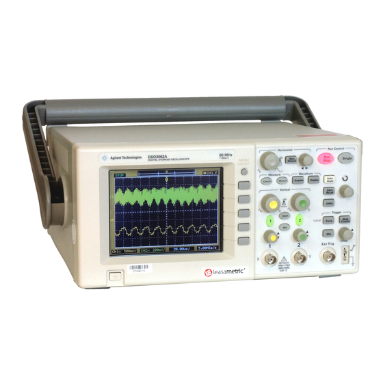
Agilent Technologies 3000 Series User's And Service Manual (156 pages)
Brand:
Agilent Technologies
| Category:
Test Equipment
| Size: 1.93 MB
Table of Contents
Safety Notices
2
Agilent 3000 Series Oscilloscopes-At a Glance
3
In this Book
4
Table of Contents
5
Figures
13
Tables
15
1 Getting Started
17
Step 1. Inspect the Package Contents
18
Figure 1 Package Contents
19
Table 1. Power Cords
20
Step 2. Turn on the Oscilloscope
21
Step 3. Load the Default Oscilloscope Setup
22
Figure 2 Save/Recall Button
22
Step 4. Input a Waveform
23
Step 5. Become Familiar with the Front Panel Controls
24
Figure 3. Front Panel
24
Figure 4. Menu Buttons
26
Using the Oscilloscope Menus
26
Step 6. Become Familiar with the Oscilloscope Display
28
Figure 5. Oscilloscope Display
28
Step 7. Use Auto-Scale
29
Figure 6 Auto-Scale Button
29
Table 2. Auto-Scale Default Settings
30
Step 8. Compensate Probes
31
Low Frequency Compensation
31
Figure 7 Low Frequency Probe Compensation
31
High Frequency Compensation
32
Figure 8 High Frequency Probe Compensation
32
Step 9. Use the Run Control Buttons
33
Figure 9 Run Control Buttons
33
2 Displaying Data
35
Using the Horizontal Controls
36
Figure 10 Horizontal Controls
36
Figure 11. Status Bar, Trigger Position, and Horizontal Scale Indicators
37
To Adjust the Horizontal Scale
38
To Adjust the Horizontal Position
39
To Display the Delayed Sweep Time Base
39
Figure 12 Delayed Sweep Time Base Window
40
To Change the Horizontal Time Base (Y-T or X-Y)
40
Figure 13 X-Y Display Format Showing In-Phase Waveforms
41
Figure 14 Trigger Holdoff
42
To Reset the Trigger Offset
42
To Specify a Trigger Holdoff
42
To View the Sample Rate
43
Using the Vertical Controls
44
Figure 15 Vertical Controls
44
To Adjust the Vertical Scale
45
To Turn Waveforms on or off (Channel, Math, or Reference)
45
To Adjust the Vertical Position
46
To Specify Channel Coupling
46
Figure 16 DC Coupling Control
47
Figure 17 AC Coupling Control
47
Figure 18 GND Coupling Control
48
To Specify a Bandwidth Limit
48
Figure 19 BW Limit Control on
49
Figure 20 BW Limit Control off
49
Figure 21 Probe Attenuation Set to 1000:1
50
To Specify the Probe Attenuation
50
To Invert a Waveform
51
To Use a Digital Filter
51
Figure 22 Waveform before Inversion
52
Figure 23 Waveform after Inversion
52
Using Math Function Waveforms
53
Figure 24 Math Scale Setting Value
53
To Add, Subtract, or Multiply Waveforms
54
To Display the Frequency Domain Using FFT
54
Table 3 FFT Window Characteristics
55
Figure 25 FFT Waveform
56
Using a Reference Waveform
57
To Save a Reference Waveform
57
To Position, Scale, and Invert a Reference Waveform
57
Changing the Display Settings
58
To Display Waveforms as Vectors or Dots
58
To Change the Grid
58
Figure 26 Display Button
58
To Use Waveform Persistence
59
To Clear the Display
59
To Adjust the Display Brightness
59
To Change the Menu Display Time
59
To Invert Screen Colors
60
3 Capturing Data
61
Overview of Sampling
62
Sampling Theory
62
Aliasing
62
Oscilloscope Bandwidth and Sample Rate
63
Figure 27 Alaising
63
Figure 28 Theoretical Brick-Wall Frequency Response
64
Oscilloscope Rise Time
65
Figure 29. Sample Rate and Oscilloscope Bandwidth
65
Oscilloscope Bandwidth Required
66
Memory Depth and Sample Rate
67
Choosing the Sampling Mode
68
Figure 30 Acquire Button
68
Figure 31 Real-Time Sampling Mode
69
To Select the Real-Time Sampling Mode
69
Figure 32 Equivalent-Time (Repetitive) Sampling Mode
70
To Select the Equivalent-Time Sampling Mode
70
Choosing the Acquisition Mode
72
To Select the Normal Acquisition Mode
72
To Select the Average Acquisition Mode
72
Figure 33 Noisy Waveform Without Averaging
73
Figure 34 Noisy Waveform with Averaging
73
To Select the Peak Detect Acquisition Mode
74
Figure 35 Peak Detect Waveform
74
Adjusting the Trigger Level
76
To Adjust the Trigger Level
76
Figure 36 Trigger Controls
76
To Force a Trigger
77
Choosing the Trigger Mode
78
To Set up Edge Triggers
78
To Set up Pulse Width Triggers
79
To Set up Video Triggers
80
Figure 37 Line Synchronization
81
Figure 38 Field Synchronization
81
Setting Other Trigger Parameters
82
To Set the Trigger Sweep
82
To Set the Trigger Coupling
82
Using the External Trigger Input
83
Recording/Playing-Back Waveforms
83
To Record Waveforms
83
To Play-Back Waveforms
84
To Store Recorded Waveforms
86
4 Making Measurements
87
Displaying Automatic Measurements
88
To Display an Automatic Measurement
88
Figure 39 Measure Button
88
To Clear Automatic Measurements from the Display
89
To Display or Hide All Automatic Measurements
89
Voltage Measurements
90
Vpp (Peak-To-Peak Voltage)
90
Figure 40 Voltage Measurement Points
90
Vmax (Maximum Voltage)
91
Vmin (Minimum Voltage)
91
Vavg (Average Voltage)
91
Vamp (Amplitude Voltage = Vtop - Vbase)
91
Vtop (Top Voltage)
91
Vbase (Base Voltage)
91
Vrms (Root-Mean-Square Voltage)
92
Overshoot
92
Preshoot
92
Time Measurements
93
Frequency
93
Period
93
Rise Time
94
Fall Time
94
Figure 41. Period and Frequency Measurements
94
Figure 42. Rise Time and Fall Time Measurements
94
Positive Pulse Width
95
Negative Pulse Width
95
Positive Duty Cycle
95
Negative Duty Cycle
95
Figure 43. Positive Pulse Width and Negative Pulse Width Measurements
95
Delay between Rising Edges
96
Delay between Falling Edges
96
Counter (Frequency)
96
Figure 44. Delay Measurements
96
Making Cursor Measurements
98
To Use Manually Adjustable Cursors
98
Figure 45 Cursors Button
98
To Use Tracking Cross-Hair Cursors
99
To Display Cursors for Automatic Measurements
100
5 Saving, Recalling, and Printing Data
101
Saving and Recalling Waveforms and Setups
102
To Save and Load Waveforms
102
Figure 46 Save/Recall Button
102
To Save and Load Oscilloscope Setups
103
Saving to and Recalling from a USB Mass Storage Device
104
To Save/Load Waveforms To/From a USB Device
104
Figure 47 USB Module on Rear Panel
104
To Save/Load Oscilloscope Setups To/From a USB Device
105
To Save Screens to BMP Format Files (on a USB Device)
105
To Save Data to CSV Format Files (on a USB Device)
106
To Save a File to a USB Device
106
Figure 48 USB Device Save Menu
106
To Load a File from a USB Device
108
Figure 49 USB Device Load Menu
108
Printing the Display to a USB Printer
109
Supported Printers
110
6 Oscilloscope Utility Settings
111
Figure 50 Utility Button
111
Performing Mask Tests
112
To Enable/Disable Mask Tests
112
To Select the Source Channel for Mask Tests
112
To Run/Stop a Mask Test
112
To Turn On/Off the Mask Test Message Display
113
To Set the Mask Test Output Condition
113
To Stop a Mask Test on the Output Condition
113
To Set up Masks
114
Setting IO Parameters
115
Setting the Menu Language
115
Displaying System Information
116
Turning Sound on or off
116
Performing Self-Tests
117
To Perform Screen Tests
117
To Perform Key Tests
117
Figure 51 Calibration Screen
118
Running Self-Calibration
118
7 Specifications and Characteristics
119
Specifications
120
Table 4 Specifications
120
Characteristics
121
Table 5. Acquisition System Characteristics
121
Table 6. Vertical System Characteristics
121
Table 7. Horizontal System Characteristics
122
Table 8. Trigger System Characteristics
122
Table 9. Display System Characteristics
124
Table 10. Measurement Features
124
Table 11. General Characteristics
124
Table 12. Power Requirements
125
Table 13. Environmental Characteristics
125
Table 14 Other
125
8 Service
127
Testing Performance
128
Before Testing Performance
129
Table 15 Equipment Required for Performance Verification Testing
129
Vertical Performance Verification
130
DC Gain Accuracy Test
130
Table 16 DC Gain Accuracy Specification
130
Table 17 Equipment Required for DC Gain Accuracy Test
130
Figure 52 Default Setup Menu Item
131
Figure 53 Averages Menu Item
132
Figure 54. Connecting Equipment for DC Gain Accuracy Test
133
Figure 55 Vavg Menu Item
134
Analog Bandwidth - Maximum Frequency Check
135
Table 18. DC Gain Accuracy Specification
136
Table 19. Equipment Required for Performance Verification Testing
136
Figure 56. Connecting Equipment for Maximum Frequency Check Test
137
Figure 57 Default Setup Menu Item
138
Figure 58 Channel 1 Vertical Scale Setting
139
Figure 59 Channel 1 Horizontal Scale Setting
139
Figure 60 Averages Menu Item
140
Figure 61 Signal Generator Waveform
141
Table 20 Oscilloscope Models and Signal Generator Frequency
142
Performance Test Record
144
Table 21 DC Gain Test
144
Table 22 Analog Bandwidth - Maximum Frequency Check
145
Returning the Oscilloscope to Agilent for Service
146
Contacting Agilent
146
Warnings
147
A Safety Notices
148
To Clean the Instrument
148
Safety Symbols
149
Index
151
Advertisement
Agilent Technologies 3000 Series Manual (168 pages)
Brand:
Agilent Technologies
| Category:
Test Equipment
| Size: 0.9 MB
Table of Contents
Table of Contents
3
1 O Module Installation and Configuration
7
I/O Module Installation
8
I/O Module Configuration
10
2 Introduction to Programming
13
Communicating with the Oscilloscope
14
Instruction Header
14
Truncation Rule
15
White Space (Separator)
15
Braces
16
Ellipsis
16
Square Brackets
16
Program Message Terminator
16
Block Data
17
Remote Command Tips
17
3 Commands Quick Reference
19
4 Common Commands
27
CLS (Clear Status)
29
IDN? (Identification Number)
30
OPC? (Operation Complete)
31
RST (Reset)
32
5 Root Level Commands
33
Auto
35
Forcetrig
36
Run
37
Stop
38
Trig%50
39
6 Acquire Commands
41
Averages
43
Mode
44
Srate
45
Type
46
7 BEEP Commands
47
Enable
49
8 Channel<N> Commands
51
Bwlimit
53
Coupling
54
Display
55
Invert
56
Offset
57
Probe
58
Scale
59
9 Counter Commands
61
Enable
63
Value
64
10 Display Commands
65
Clear
67
Grid
68
Menudisplay
69
Persistence
70
Screen
71
11 KEY Commands
73
Commands for Front Panel Actions
75
Lock
77
12 MASK Commands
79
Enable
81
Operate
82
Output
83
Source
84
Stoponoutput
85
13 Measure Commands
89
Clear
91
Falltime
92
Frequency
93
Ndutycycle
94
Nwidth
95
Overshoot
96
Pdutycycle
97
Period
98
Preshoot
99
Pwidth
100
Risetime
101
Vamplitude
102
Vaverage
103
Vbase
104
Vmax
105
Vmin
106
Vpp
107
Vrms
108
Vtop
109
14 Saverecall Commands
111
Load
113
Location
114
Save
115
Type
116
15 Timebase Commands
117
Delayed
119
Holdoff
120
Position
121
Scale
122
Scan
123
16 Trigger Commands
125
[:Edge]:Coupling
127
[:Edge]:Level
128
[:Edge]:Slope
129
[:Edge]:Soure
130
[:Edge]:Sweep
131
Mode
132
Pulse:mode
133
Pulse:width
134
Status
135
Video:polarity
136
Video:standard
137
Video:sync
138
17 Waveform Commands
139
Data
141
Eraseofroll
142
Maxpeakdetect
143
Memorydata
144
Minpeakdetect
145
Screendata
146
Screenmax
147
Screenmin
148
Source
149
Startofroll
150
Sysmemsize
151
Tposition
152
Windowzoom
153
Winmemsize
154
Wposition
155
Xend
156
Xincrement
157
Xorigin
158
Xstart
159
Yincrement
160
Yorigin
161
Agilent Technologies 3000 Series User's And Service Manual (122 pages)
Brand:
Agilent Technologies
| Category:
Test Equipment
| Size: 2.07 MB
Table of Contents
Table of Contents
3
Getting Started
5
Inspecting the Package Contents
6
Performing a Functional Check
9
Compensating Probes
11
Front Panel and User Interface Descriptions
13
Automatically Displaying a Waveform
16
Cleaning the Oscilloscope
17
Using the Oscilloscope
19
Vertical Controls
21
Vertical System Setup
22
Channel Coupling Control
24
Bandwidth Limit Control
27
Probe Attenuation Control
29
Invert Control
30
Digital Filter Controls
32
Math Functions Control
33
Reference Control
37
Removing Waveforms from the Display
39
Horizontal Controls
40
Horizontal System Setup
41
Horizontal Knobs
42
Horizontal Menu
43
Roll Mode
47
Trigger Controls
48
Trigger System Setup
49
Trigger Modes
51
Waveform Controls
55
Stop Acquisition
56
Equivalent Time Sampling
56
Average Acquisition
56
Peak Detect
58
Sequence Capability
59
Display Controls
61
Save and Recall Controls
63
Waveforms
64
Setups
64
Default Setup
64
Load
64
Save
64
Utility Controls
65
Mask Test
67
I/O Setup Menu
69
System Info
70
Self-Calibration
71
Self-Test
72
Automatic Measurement Controls
73
Voltage Measurements
74
Time Measurements
75
Automatic Measurement Procedure
76
Measurement Concepts
77
Cursor Measurement Controls
81
Manual
82
Track
84
Auto Measure
85
Autoscale and Run/Stop Controls
86
Autoscale Button
87
Run/Stop Button
89
Specifications and Characteristics
91
Specifications
92
Characteristics
93
Service
97
Returning the Oscilloscope to Agilent Technologies for Service
98
Testing Performance
99
Before Performing Performance Verification Testing
101
DC Gain Accuracy Test
103
Analog Bandwidth - Maximum Frequency Check
109
Performance Test Record
117
Advertisement
Agilent Technologies 3000 Series Datasheet (30 pages)
Brand:
Agilent Technologies
| Category:
Test Equipment
| Size: 1.99 MB
Table of Contents
Virtual Front Panel
12
Recommended Accessories
17
Performance Characteristics
18
Vertical System Analog Channels
18
Horizontal System Analog Channels
19
Acquisition System
19
Trigger System
20
Waveform Measurements
22
Waveform Math
22
Display Characteristics
22
Nonvolatile Storage
26
Related Literature
26
Advertisement
Related Products
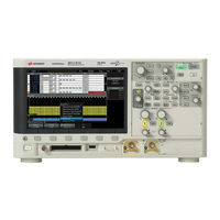
Agilent Technologies InfiniiVision 3000 X-Series
Agilent Technologies InfiniiVision 3000 MSO-X
Agilent Technologies InfiniiVision 3000 3024A MSO-X
Agilent Technologies InfiniiVision 3000 3034A
Agilent Technologies InfiniiVision 3000 X- Series
Agilent Technologies 3070 Series
Agilent Technologies InfiniiVision 3000 DSO-X 3052A
Agilent Technologies InfiniiVision 3000 DSO-X 3014A
Agilent Technologies InfiniiVision 3000 DSO-X 3034A
Agilent Poroshell 300
Agilent Technologies Categories
Measuring Instruments
Laboratory Equipment
Test Equipment
Water Pump
Power Supply
More Agilent Technologies Manuals
Login
Sign In
OR
Sign in with Facebook
Sign in with Google
Upload manual
Upload from disk
Upload from URL