Sign In
Upload
Manuals
Brands
Agilent Technologies Manuals
Switch
11713A
Agilent Technologies 11713A Manuals
Manuals and User Guides for Agilent Technologies 11713A. We have
1
Agilent Technologies 11713A manual available for free PDF download: Operating And Service Manual
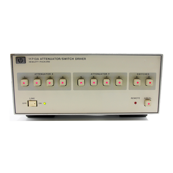
Agilent Technologies 11713A Operating And Service Manual (88 pages)
Attenuator/Switch Driver
Brand:
Agilent Technologies
| Category:
Switch
| Size: 3.14 MB
Table of Contents
Safety and Regulatory Information
6
Table of Contents
11
Agilent Technologies 11713A Attenuator/Switch Driver
14
Overview
14
Compatible Attenuators and Switches
16
Installing the Agilent Technologies 11713A Attenuator/Switch Driver
18
Initial Inspection
19
Environmental Limitations
19
Preparing for Use
19
Verifying Requirements
20
Figure 2-1 Line Voltage Selection
21
GPIB Addressing
22
Figure 2-2 GPIB Address Selection
22
Table 2-1 ASCII Address Codes to Decimal Equivalents
22
Mating Connectors
23
Figure 2-3 General Purpose Interface Bus Connection
23
Connecting to Attenuators and Switches
24
Table 2-2 Attenuator Cable Connector Pin Numbers and Wire Color Codes
25
Driving Additional Coaxial Switches
26
Figure 2-4 Connections for Coaxial Switches
26
Figure 2-5 Connections for Agilent 8761B SPDT Switches
27
Connecting to Four-Section
28
Figure 2-6 Typical Connections for Programmable Four-Section Attenuator
28
Connecting to Relays
29
Figure 2-7 Relay Driving Circuit
29
Verifying Performance
29
Specifications
30
Supplemental Characteristics
31
Table 3-1 Specifications
31
Table 3-2 Supplemental Characteristics
31
Verification
32
Recommended Test Equipment
33
Table 4-1 Recommended Test Equipment
33
Operator's Check for Local Operation
34
Figure 4-1 Local Operation Test Setup
34
GPIB Interface Check for Remote Operation
36
Figure 4-2 GPIB Interface Check Test Setup
36
Receiving the Message
37
Remote Message
37
Local Operation
39
Local Control
40
Figure 5-L Front Panel Features
41
Figure 5-2 Rear Panel Features
42
Remote Operation
43
GPIB Compatibility
44
Remote Mode
44
Local Mode
44
Addressing
45
Data Messages
45
Receiving the Data Message
45
Sending the Data Message
46
Receiving the Trigger Message
46
Receiving the Clear Message
46
Receiving the Local Lockout Message
47
Receiving the Clear Lockout/Set Local Message
47
Receiving the Pass Control Message
47
Sending the Require Service Message
47
Sending the Status Byte Message
47
Sending the Status Bit Message
47
Table 6-1 GPIB Message Reference Table
48
Table 6-2 GPIB Control Statement Results
49
Table 6-3 Attenuation Levels and Corresponding Data Strings
50
Replacing Major Assemblies
51
Replaceable Parts
52
Table 7-1 Accessories Supplied
52
Table 7-2 Line Fuse Part Numbers
52
Table 7-3 Major Assemblies
53
Table 7-4 Major Cables
53
Table 7-5 Cabinet Parts
54
Module Cover Removal/Replacement
55
Front Panel Removal/Replacement
56
Rear Panel Removal/Replacement
57
A1 Interconnect and Power Supply Assembly Removal/Replacement
58
A2 Driver Assembly Removal/Replacement
59
A3 Latch Assembly Removal/Replacement
60
A4 Remote Local Logic Assembly Removal/Replacement
61
A5 GPIB Handshake Data Input Assembly Removal/Replacement
62
A6 Interface Assembly Removal/Replacement
63
A7 Switch Board Assembly Removal/Replacement
64
A8 Power Supply/Line Filter Assembly Removal/Replacement
65
Servicing the Attenuator/Switch Driver
66
Preparing a Static-Safe Workstation
67
Figure 8-1 Static-Safe Work Station
67
Reducing ESD Damage
67
Table 8-1 Static-Safe ESD Accessories
68
Maintenance and Adjustments
69
Fuse Removal/Replacement
69
Adjustments
69
Troubleshooting
70
Isolating a Malfunction
70
Parts Identification
72
Figure 8-2 11713A Attenuator/Switch Driver Top Cover Removed
73
Figure 8-3 11713A Attenuator Switch Driver Bottom Cover Removed
74
11713A Simplified Block Diagram
75
Troubleshooting the A1 Interconnect Assembly
76
Troubleshooting the A2 Driver Assembly
77
Troubleshooting the A3 Latch Assembly
79
Troubleshooting the A4 Local Logic Assembly
80
Troubleshooting the A5 Handshake and Data Input Assembly
81
Troubleshooting the A6 Interface Assembly
83
Troubleshooting the A7 Switch Board Assembly
84
The A8 Power Supply/Line Module Assembly
86
Advertisement
Advertisement
Related Products
Agilent Technologies 11713B
Agilent Technologies 11713C
Agilent Technologies 1170 Series
Agilent Technologies 1170A
Agilent Technologies 1171A
Agilent Technologies 1172A
Agilent Technologies 1173A
Agilent Technologies 1159A
Agilent Technologies 11896A
Agilent Technologies 11982A
Agilent Technologies Categories
Measuring Instruments
Laboratory Equipment
Test Equipment
Water Pump
Power Supply
More Agilent Technologies Manuals
Login
Sign In
OR
Sign in with Facebook
Sign in with Google
Upload manual
Upload from disk
Upload from URL