Advantech Automation1 iXC4e Manuals
Manuals and User Guides for Advantech Automation1 iXC4e. We have 2 Advantech Automation1 iXC4e manuals available for free PDF download: Hardware Manual
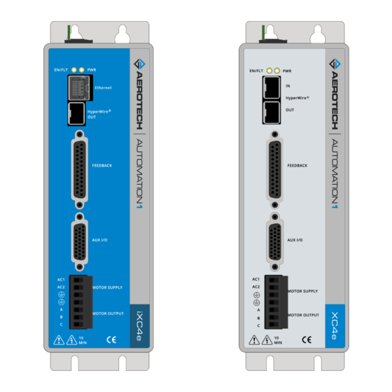
Advantech Automation1 iXC4e Hardware Manual (124 pages)
PWM High-Performance Digital Drives
Table of Contents
-
-
Dimensions27
-
-
Sync Port88
-
-
Advertisement
Advantech Automation1 iXC4e Hardware Manual (124 pages)
PWM High-Performance Digital Drives
Table of Contents
-
-
Dimensions24
-
-
Sync Port88
-
-
-
-
Index117
-