
Subscribe to Our Youtube Channel
Related Manuals for Advantech Automation1 iXC4e


Summary of Contents for Advantech Automation1 iXC4e
-
Page 1: Automation1 Ixc4E And Xc4E Pwm High-Performance Digital Drives
Automation1 iXC4e and XC4e PWM High-Performance Digital Drives HARDWARE MANUAL Revision 2.02... - Page 2 GLOBAL TECHNICAL SUPPORT Go to the Global Technical Support Portal for information and support about your Aerotech, Inc. products. The website supplies software, product manuals, Help files, training schedules, and PC-to-PC remote technical support. If necessary, you can complete Product Return (RMA) forms and get information about repairs and spare or replacement parts.
-
Page 3: Table Of Contents
Hardware Manual Table of Contents Table of Contents Automation1 iXC4e and XC4e PWM High-Performance Digital Drives Table of Contents List of Figures List of Tables EU Declaration of Conformity Agency Approvals Safety Procedures and Warnings Installation Overview Chapter 1: Introduction 1.1. - Page 4 Table of Contents iXC4e/XC4e Hardware Manual 2.5.7. Analog Input 0 (Differential) 2.6. Brake Power Supply Connector 2.7. HyperWire Interface 2.8. External Shunt Option [-SX1] 2.9. Sync Port 2.10. System Interconnection 2.11. PC Configuration and Operation Information Chapter 3: -EB1 I/O Option Board 3.1.
-
Page 5: List Of Figures
iXC4e/XC4e Hardware Manual List of Figures List of Figures Figure 1-1: iXC4e Digital Drive-Based Controller Figure 1-2: XC4e Digital Drive Figure 1-3: Functional Diagram Figure 1-4: Dimensions Figure 1-5: Dimensions [-EB1] Figure 2-1: Control Supply Connections Figure 2-2: Motor Supply Connections Figure 2-3: TV0.3-28-56-ST Transformer Control and Motor Power Wiring (40 VDC Bus) Figure 2-4:... - Page 6 List of Figures iXC4e/XC4e Hardware Manual Figure 2-44: High-Speed Inputs Figure 2-45: Analog Output 0 Schematic Figure 2-46: Analog Input 0 Schematic Figure 2-47: Drive-Based System Wiring Drawing (Best Practice) Figure 2-48: PC-Based System Wiring Drawing (Best Practice) Figure 2-49: Drive-Based Controller System Interconnection (Best Practice) Figure 2-50: PC-Based Controller System Interconnection (Best Practice)
-
Page 7: List Of Tables
iXC4e/XC4e Hardware Manual List of Tables List of Tables Table 1-1: Features and Options Table 1-2: Electrical Specifications Table 1-3: Mounting Specifications Table 1-4: Environmental Specifications Table 1-5: Drive and Software Compatibility Table 2-1: Control Supply Wiring Specifications Table 2-2: Mating Connector Part Numbers for the Control Supply Connector Table 2-3: Motor Supply Connector Wiring Specifications Table 2-4:... - Page 8 List of Tables iXC4e/XC4e Hardware Manual Table 2-44: High-Speed Input Specifications Table 2-45: High-Speed Input Pins on the Auxiliary I/O Connector Table 2-46: Analog Output Specifications Table 2-47: Analog Output Pins on the Auxiliary I/O Connector Table 2-48: Analog Input Specifications Table 2-49: Analog Input Pins on the Auxiliary I/O Connector Table 2-50:...
-
Page 9: Eu Declaration Of Conformity
iXC4e/XC4e Hardware Manual EU Declaration of Conformity EU Declaration of Conformity Manufacturer Aerotech, Inc. Address 101 Zeta Drive Pittsburgh, PA 15238-2811 Product iXC4e/XC4e Model/Types This is to certify that the aforementioned product is in accordance with the applicable requirements of the following directive(s): 2014/30/EU Electromagnetic Compatibility (EMC) - Page 10 EU Declaration of Conformity iXC4e/XC4e Hardware Manual This page intentionally left blank. www.aerotech.com...
-
Page 11: Agency Approvals
iXC4e/XC4e Hardware Manual Agency Approvals Agency Approvals Aerotech tested its XC4e drives and found that they obey the standards that follow: IMPORTANT: iXC4e certification is pending. Approval: CUS NRTL Approving Agency: TUV SUD America Inc. Certificate #: U8V 068995 0028 Rev. 02 Standards: CAN/CSA-C22.2 No. - Page 12 Agency Approvals iXC4e/XC4e Hardware Manual This page intentionally left blank. www.aerotech.com...
-
Page 13: Safety Procedures And Warnings
iXC4e/XC4e Hardware Manual Safety Procedures and Warnings Safety Procedures and Warnings IMPORTANT: This manual tells you how to carefully and correctly use and operate the drive. Read all parts of this manual before you install or operate the drive or before you do maintenance to your system. - Page 14 Safety Procedures and Warnings iXC4e/XC4e Hardware Manual This page intentionally left blank. www.aerotech.com...
-
Page 15: Installation Overview
iXC4e/XC4e Hardware Manual Installation Overview Installation Overview The images that follow show the order in which to make connections and settings that are typical to the iXC4e/XC4e. If a custom interconnect drawing was supplied with your system, that drawing is on your Storage Device and shows as a line item on your Sales Order in the Integration section. - Page 16 Installation Overview iXC4e/XC4e Hardware Manual Connect the motor to the amplifier Motor Output connector. Section 2.2. Connect the motor to the amplifier Feedback connector. Section 2.3. Connect a PC or drive-based controller HyperWire port to the HyperWire In Section 2.7. port. Connect additional I/O as required by your application Section 2.5./...
-
Page 17: Chapter 1: Introduction
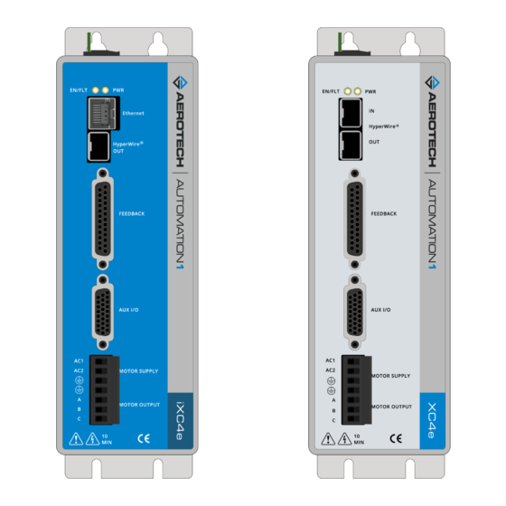
iXC4e/XC4e Hardware Manual Chapter 1: Introduction Chapter 1: Introduction The iXC4e is a high-performance digital drive-based controller. It runs the Automation1-iSMC controller to generate commands for itself as well as for additional drives on the chain. The XC4e is a high performance digital drive. The XC4e is based on the HyperWire communication protocol and receives commands from a PC or drive-based controller. -
Page 18: Figure 1-2: Xc4E Digital Drive
Chapter 1: Introduction iXC4e/XC4e Hardware Manual Figure 1-2: XC4e Digital Drive www.aerotech.com... -
Page 19: Table 1-1: Features And Options
iXC4e/XC4e Hardware Manual Chapter 1: Introduction Table 1-1: Features and Options Standard Features 100-240 VAC control supply inputs Section 2.1.1. 0-240 VAC motor supply inputs (producing 340 VDC) Section 2.1.2. Line driver square wave quadrature encoder input for position and velocity feedback Section 2.3.1. -
Page 20: Figure 1-3: Functional Diagram
Chapter 1: Introduction iXC4e/XC4e Hardware Manual The block diagram that follows shows a summary of the connector signals. Figure 1-3: Functional Diagram www.aerotech.com... -
Page 21: Electrical Specifications
iXC4e/XC4e Hardware Manual 1.1. Electrical Specifications 1.1. Electrical Specifications Table 1-2: Electrical Specifications Description -10 Option -20 Option -30 Option Input Voltage 0-240 VAC Input Frequency 50-60 Hz 34 A @ 240 V Inrush Current Motor Supply Max Continuous 10 A 10 A Input Current Input Current... -
Page 22: System Power Requirements
1.1.1. System Power Requirements iXC4e/XC4e Hardware Manual 1.1.1. System Power Requirements The following equations can be used to determine total system power requirements. The actual power required from the mains supply will be the combination of actual motor power (work), motor resistance losses, and efficiency losses in the power electronics or power transformer. -
Page 23: Mechanical Specifications
iXC4e/XC4e Hardware Manual 1.2. Mechanical Specifications 1.2. Mechanical Specifications 1.2.1. Mounting and Cooling Install the drive in an IP54 compliant enclosure to comply with safety standards. Make sure that there is sufficient clearance surrounding the drive for free airflow and for the cables and connections. IMPORTANT: The amount of airflow required to keep the drive temperature within a sufficient range is dependent on the operating conditions. -
Page 24: Dimensions
1.2.2. Dimensions iXC4e/XC4e Hardware Manual 1.2.2. Dimensions NOTE: iXC4e and XC4e dimensions are the same. iXC4e is shown. Figure 1-4: Dimensions www.aerotech.com... -
Page 25: Figure 1-5: Dimensions [-Eb1]
iXC4e/XC4e Hardware Manual 1.2.2. Dimensions NOTE: iXC4e-EB1 and XC4e-EB1 dimensions are the same. iXC4e-EB1 is shown. Figure 1-5: Dimensions [-EB1] www.aerotech.com... -
Page 26: Environmental Specifications
1.3. Environmental Specifications iXC4e/XC4e Hardware Manual 1.3. Environmental Specifications Table 1-4: Environmental Specifications Operating: 0° to 40°C (32° to 104° F) Ambient Temperature Storage: -30° to 85°C (-22° to 185° F) Humidity The maximum relative humidity is 80% for temperatures that are less than 31°C and decreases linearly to 50% relative humidity at 40°C. -
Page 27: Drive And Software Compatibility
Last Software Version column, drives that show a specific version number are not supported after that version. Table 1-5: Drive and Software Compatibility Drive Type Software First Software Version Last Software Version Automation1 iXC4e Automation1 2.0.0 Current Automation1 1.2.0 Current Automation1 XC4e A3200 6.04... - Page 28 1.4. Drive and Software Compatibility iXC4e/XC4e Hardware Manual This page intentionally left blank. www.aerotech.com...
-
Page 29: Chapter 2: Installation And Configuration
iXC4e/XC4e Hardware Manual Chapter 2: Installation and Configuration Chapter 2: Installation and Configuration Unpacking the Chassis IMPORTANT: All electronic equipment and instrumentation is wrapped in antistatic material and packaged with desiccant. Ensure that the antistatic material is not damaged during unpacking. Inspect the container of the iXC4e/XC4e for any evidence of shipping damage. -
Page 30: Input Power Connections
2.1. Input Power Connections iXC4e/XC4e Hardware Manual 2.1. Input Power Connections The iXC4e/XC4e has two AC input power connectors. One connector is for control power and the other connector is for motor power. For a full list of electrical specifications, refer to Section 1.1. Refer to Section 2.10. -
Page 31: Motor Supply Connector
iXC4e/XC4e Hardware Manual 2.1.2. Motor Supply Connector 2.1.2. Motor Supply Connector Motor power is applied to the AC1 and AC2 terminals of the iXC4e/XC4e Motor Supply connector. Peak Current Option -10: The AC1 input is internally connected to a 5 A fuse. Peak Current Option -20 and -30: The AC1 input is internally connected to a 10 A fuse. -
Page 32: Transformer Options
2.1.3. Transformer Options iXC4e/XC4e Hardware Manual 2.1.3. Transformer Options You can connect an external isolation transformer to the Motor Supply AC Input to reduce the operating voltage of the motor. Using a transformer can also reduce electrical noise. Table 2-5: Nominal Motor Operating Voltages / Required AC Voltages AC Voltage DC Voltage Table 2-6:... -
Page 33: Figure 2-3: Tv0.3-28-56-St Transformer Control And Motor Power Wiring (40 Vdc Bus)
iXC4e/XC4e Hardware Manual 2.1.3. Transformer Options Figure 2-3: TV0.3-28-56-ST Transformer Control and Motor Power Wiring (40 VDC Bus) www.aerotech.com... -
Page 34: Figure 2-4: Tv0.3-28-56-St Transformer Control And Motor Power Wiring (80 Vdc Bus)
2.1.3. Transformer Options iXC4e/XC4e Hardware Manual Figure 2-4: TV0.3-28-56-ST Transformer Control and Motor Power Wiring (80 VDC Bus) www.aerotech.com... -
Page 35: Figure 2-5: Tv0.3-28-56-St Transformer Control And Motor Power Wiring (160 Vdc Bus)
iXC4e/XC4e Hardware Manual 2.1.3. Transformer Options Figure 2-5: TV0.3-28-56-ST Transformer Control and Motor Power Wiring (160 VDC Bus) www.aerotech.com... -
Page 36: Figure 2-6: Tv0.3-28 Transformer Control And Motor Power Wiring (40 Vdc Bus)
2.1.3. Transformer Options iXC4e/XC4e Hardware Manual Figure 2-6: TV0.3-28 Transformer Control and Motor Power Wiring (40 VDC Bus) www.aerotech.com... -
Page 37: Figure 2-7: Tv0.3-56 Transformer Control And Motor Power Wiring (80 Vdc Bus)
iXC4e/XC4e Hardware Manual 2.1.3. Transformer Options Figure 2-7: TV0.3-56 Transformer Control and Motor Power Wiring (80 VDC Bus) www.aerotech.com... -
Page 38: Figure 2-8: Tm3/Tm5 Transformer Control And Motor Power Wiring
2.1.3. Transformer Options iXC4e/XC4e Hardware Manual Figure 2-8: TM3/TM5 Transformer Control and Motor Power Wiring www.aerotech.com... -
Page 39: Minimizing Noise For Emc/Ce Compliance
iXC4e/XC4e Hardware Manual 2.1.4. Minimizing Noise for EMC/CE Compliance 2.1.4. Minimizing Noise for EMC/CE Compliance IMPORTANT: The iXC4e/XC4e is a component designed to be integrated with other electronics. EMC testing must be conducted on the final product configuration. To reduce electrical noise, observe the following motor feedback and input power wiring techniques. 1. -
Page 40: Motor Power Output Connector
2.2. Motor Power Output Connector iXC4e/XC4e Hardware Manual 2.2. Motor Power Output Connector DANGER: Before you do maintenance to the equipment, disconnect the electrical power. Wait at least ten (10) minutes after removing the power supply before doing maintenance or an inspection. Otherwise, there is the danger of electric shock. The iXC4e/XC4e can be used to drive the following motor types: Brushless (refer to Section... -
Page 41: Brushless Motor Connections
iXC4e/XC4e Hardware Manual 2.2.1. Brushless Motor Connections 2.2.1. Brushless Motor Connections The configuration shown in Figure 2-9 is an example of a typical brushless motor connection. Figure 2-9: Brushless Motor Configuration Table 2-9: Wire Colors for Aerotech-Supplied Brushless Motor Cables Wire Color Set 1 Wire Color Set 2 Wire Color Set 3... -
Page 42: Brushless Motor Powered Motor And Feedback Phasing
2.2.1. Brushless Motor Connections iXC4e/XC4e Hardware Manual 2.2.1.1. Brushless Motor Powered Motor and Feedback Phasing Observe the state of the encoder and Hall-effect device signals in the Diagnostics section of the Status Utility. Table 2-10: Hall Signal Diagnostics Hall-Signal Status Definition 0 V or logic low 5 V or logic high... -
Page 43: Brushless Motor Unpowered Motor And Feedback Phasing
iXC4e/XC4e Hardware Manual 2.2.1. Brushless Motor Connections 2.2.1.2. Brushless Motor Unpowered Motor and Feedback Phasing Disconnect the motor from the controller and connect the motor in the test configuration shown in Figure 2-12. This method will require a two-channel oscilloscope, a 5V power supply, and six resistors (10,000 ohm, 1/4 watt). -
Page 44: Dc Brush Motor Connections
2.2.2. DC Brush Motor Connections iXC4e/XC4e Hardware Manual 2.2.2. DC Brush Motor Connections The configuration shown in Figure 2-14 is an example of a typical DC brush motor connection. Refer to Section 2.2.2.1. for information on motor phasing. Figure 2-14: DC Brush Motor Configuration Table 2-11: Wire Colors for Aerotech-Supplied DC Brush Motor Cables Wire Color Set 1... -
Page 45: Dc Brush Motor Phasing
iXC4e/XC4e Hardware Manual 2.2.2. DC Brush Motor Connections 2.2.2.1. DC Brush Motor Phasing A properly phased motor means that the positive motor lead should be connected to the ØA motor terminal and the negative motor lead should be connected to the ØC motor terminal. To determine if the motor is properly phased, connect a voltmeter to the motor leads of an un-powered motor: 1. -
Page 46: Stepper Motor Connections
2.2.3. Stepper Motor Connections iXC4e/XC4e Hardware Manual 2.2.3. Stepper Motor Connections The configuration shown in Figure 2-16 is an example of a typical stepper motor connection. Refer to Section 2.2.3.1. for information on motor phasing. In this case, the effective motor voltage is half of the applied bus voltage. For example, an 80V motor bus supply is needed to get 40V across the motor. -
Page 47: Stepper Motor Phasing
iXC4e/XC4e Hardware Manual 2.2.3. Stepper Motor Connections 2.2.3.1. Stepper Motor Phasing A stepper motor can be run with or without an encoder. Without an Encoder: You do not need to phase the motor. With an Encoder: Because the end of travel (EOT) limit inputs are relative to motor rotation, it is important to phase the motor. -
Page 48: Feedback Connector
2.2.3. Stepper Motor Connections iXC4e/XC4e Hardware Manual 2.3. Feedback Connector The connector pin assignment is shown in Table 2-13 with detailed connection information in the following sections. Table 2-13: Feedback Connector Pinout Pin # Description In/Out/Bi Connector Reserved Motor Over Temperature Thermistor Input +5V Power Plug and Play Serial Data (for Aerotech stages only) -
Page 49: Primary Encoder Inputs
iXC4e/XC4e Hardware Manual 2.3.1. Primary Encoder Inputs 2.3.1. Primary Encoder Inputs The primary encoder inputs are accessible through the Feedback connector. Use the PrimaryFeedbackType [A3200: PositionFeedbackType or VelocityFeedbackType] parameter to configure the iXC4e/XC4e to accept an encoder signal type. Square Wave encoder signals: Section 2.3.1.1. -
Page 50: Square Wave Encoder
2.3.1. Primary Encoder Inputs iXC4e/XC4e Hardware Manual 2.3.1.1. Square Wave Encoder The drive accepts RS-422 square wave encoder signals. The drive will generate a feedback fault if it detects an invalid signal state caused by an open or shorted signal connection. Use twisted-pair wiring for the highest performance and noise immunity. -
Page 51: Absolute Encoder
iXC4e/XC4e Hardware Manual 2.3.1. Primary Encoder Inputs 2.3.1.2. Absolute Encoder The drive retrieves absolute position data along with encoder fault information through a serial data stream from the absolute encoder. Use twisted-pair wiring for the highest performance and noise immunity. You cannot echo an absolute encoder signal. Refer to Figure 2-19 for the serial data stream interface. -
Page 52: Sine Wave Encoder [-Mx2/-Mx3 Option]
2.3.1. Primary Encoder Inputs iXC4e/XC4e Hardware Manual 2.3.1.3. Sine Wave Encoder [-MX2/-MX3 Option] The Sine Wave Encoder option provides higher positioning resolution by subdividing the fundamental output period of the encoder into smaller increments. The amount of subdivision is specified by the PrimaryEncoderMultiplicationFactor [A3200: EncoderMultiplicationFactor] parameter. -
Page 53: Figure 2-21: Sine Wave Encoder Schematic (Feedback Connector)
iXC4e/XC4e Hardware Manual 2.3.1. Primary Encoder Inputs Figure 2-21: Sine Wave Encoder Schematic (Feedback Connector) www.aerotech.com... -
Page 54: Encoder Phasing
2.3.1. Primary Encoder Inputs iXC4e/XC4e Hardware Manual 2.3.1.4. Encoder Phasing Incorrect encoder polarity will cause the system to fault when enabled or when a move command is issued. Figure 2-22 illustrates the proper encoder phasing for clockwise motor rotation (or positive forcer movement for linear motors). -
Page 55: Hall-Effect Inputs
iXC4e/XC4e Hardware Manual 2.3.2. Hall-Effect Inputs 2.3.2. Hall-Effect Inputs The Hall-effect switch inputs are recommended for AC brushless motor commutation but not absolutely required. The Hall-effect inputs accept 5 VDC level signals. Hall states (0,0,0) or (1,1,1) are invalid and will generate a "Hall Fault"... -
Page 56: Thermistor Input
2.3.3. Thermistor Input iXC4e/XC4e Hardware Manual 2.3.3. Thermistor Input The thermistor input is used to detect a motor over temperature condition by using a positive temperature coefficient sensor. As the temperature of the sensor increases, so does the resistance. Under normal operating conditions, the resistance of the thermistor is low which will result in a low input signal. -
Page 57: Encoder Fault Input
iXC4e/XC4e Hardware Manual 2.3.4. Encoder Fault Input 2.3.4. Encoder Fault Input The encoder fault input is for use with encoders that have a fault output. This is provided by some manufactures and indicates a loss of encoder function. The active state of this input is parameter configurable and the controller should be configured to disable the axis when the fault level is active. -
Page 58: End Of Travel And Home Limit Inputs
2.3.5. End of Travel and Home Limit Inputs iXC4e/XC4e Hardware Manual 2.3.5. End of Travel and Home Limit Inputs End of Travel (EOT) limits are required to define the end of the physical travel on linear axes. Positive or clockwise motion is stopped by the clockwise (CW) end of travel limit input. Negative or counterclockwise motion is stopped by the counterclockwise (CCW) end of travel limit input. -
Page 59: Figure 2-27: End Of Travel And Home Limit Input Connections
iXC4e/XC4e Hardware Manual 2.3.5. End of Travel and Home Limit Inputs Figure 2-27: End of Travel and Home Limit Input Connections Figure 2-28: End of Travel and Home Limit Input Schematic (Feedback Connector) www.aerotech.com... -
Page 60: End Of Travel And Home Limit Phasing
2.3.5. End of Travel and Home Limit Inputs iXC4e/XC4e Hardware Manual 2.3.5.1. End of Travel and Home Limit Phasing If the EOT limits are reversed, you will be able to move further into a limit but be unable to move out. To correct this, swap the connections to the CW and CCW inputs at the Feedback connector or swap the CW and CCW limit functionality in the software using the EndOfTravelLimitSetup parameter. -
Page 61: Brake Outputs
iXC4e/XC4e Hardware Manual 2.3.6. Brake Outputs 2.3.6. Brake Outputs The iXC4e/XC4e has a dedicated brake control circuit. Configure the brake with the BrakeSetup [A3200: EnableBrakeControl] parameter for automatic control (typical). You can also use software commands to directly control the brake output. Refer to Section 2.6. -
Page 62: Safe Torque Off Input (Sto)
2.4. Safe Torque Off Input (STO) iXC4e/XC4e Hardware Manual 2.4. Safe Torque Off Input (STO) IMPORTANT: iXC4e certification is pending. The STO circuit is comprised of two identical channels, each of which must be energized in order for the drive to produce motion. Each STO input is opto-isolated and accepts 24 V levels directly without the need for external current limiting resistors. -
Page 63: Figure 2-31: Typical Configuration
iXC4e/XC4e Hardware Manual 2.4. Safe Torque Off Input (STO) Table 2-27: STO Electrical Specifications Status Value STO off (motion allowed) 18-24 V, 7 ma STO on (safe state entered, no motion) 0-6 V 22-26 AWG (0.5 - 0.14 mm Recommended Wire Gauge STO System Power Supply PELV STO Wire Length (maximum) -
Page 64: Sto Standards
2.4. Safe Torque Off Input (STO) iXC4e/XC4e Hardware Manual 2.4.1. STO Standards Table 2-28 describes and specifies the safety requirements at the system level for the Safe Torque Off (STO) feature of the drive. This assumes that diagnostic testing is performed according to Section 2.4.4. -
Page 65: Sto Functional Description
iXC4e/XC4e Hardware Manual 2.4. Safe Torque Off Input (STO) 2.4.2. STO Functional Description The motor can only be activated when voltage is applied to both STO 1 and STO 2 inputs. The STO state will be entered if power is removed from either the STO 1 or the STO 2 inputs. When the STO state is entered, the motor cannot generate torque or force and is therefore considered safe. -
Page 66: Sto Startup Validation Testing
2.4. Safe Torque Off Input (STO) iXC4e/XC4e Hardware Manual Non-standard STO delay times are provided by special factory order. In this case, the non-standard STO delay time is indicated by a label placed on the slice amplifier’s main connector (STO DELAY = xx sec). Table 2-30: STO Signal Delay Value... -
Page 67: Sto Diagnostics
iXC4e/XC4e Hardware Manual 2.4. Safe Torque Off Input (STO) 2.4.4. STO Diagnostics Activation of STO means removing power from the drive’s STO inputs. This is typically done by pressing the emergency stop switch. The drive initiates a diagnostic check every time the STO is activated after the Diagnostic Test Delay Time has elapsed. -
Page 68: Auxiliary I/O Connector
2.5. Auxiliary I/O Connector iXC4e/XC4e Hardware Manual 2.5. Auxiliary I/O Connector The Auxiliary I/O connector has 1 analog input, 6 digital inputs, 1 analog output, 4 digital outputs, a secondary line driver encoder input, and a secondary absolute encoder interface. Table 2-33: Auxiliary I/O Connector Pinout Pin# Description... -
Page 69: Auxiliary Encoder Inputs
iXC4e/XC4e Hardware Manual 2.5. Auxiliary I/O Connector 2.5.1. Auxiliary Encoder Inputs The Auxiliary Encoder connector gives you a second encoder input channel. This channel is typically used for dual loop applications. Use the AuxiliaryFeedbackType [A3200: PositionFeedbackType or VelocityFeedbackType] parameter to configure the iXC4e/XC4e to accept an encoder signal type. -
Page 70: Square Wave Encoder
2.5. Auxiliary I/O Connector iXC4e/XC4e Hardware Manual 2.5.1.1. Square Wave Encoder The drive accepts RS-422 square wave encoder signals. The drive will generate a feedback fault if it detects an invalid signal state caused by an open or shorted signal connection. Use twisted-pair wiring for the highest performance and noise immunity. -
Page 71: Absolute Encoder
iXC4e/XC4e Hardware Manual 2.5. Auxiliary I/O Connector 2.5.1.2. Absolute Encoder The drive retrieves absolute position data along with encoder fault information through a serial data stream from the absolute encoder. Use twisted-pair wiring for the highest performance and noise immunity. You cannot use an absolute encoder with incremental signals on the Auxiliary I/O Connector. Refer to Figure 2-34 for the serial data stream interface. -
Page 72: Sine Wave Encoder [-Mx3 Option]
2.5. Auxiliary I/O Connector iXC4e/XC4e Hardware Manual 2.5.1.3. Sine Wave Encoder [-MX3 Option] The Sine Wave Encoder option provides higher positioning resolution by subdividing the fundamental output period of the encoder into smaller increments. The amount of subdivision is specified by the AuxiliaryEncoderMultiplicationFactor parameter. -
Page 73: Figure 2-36: Sine Wave Encoder Schematic (Auxiliary I/O Connector)
iXC4e/XC4e Hardware Manual 2.5. Auxiliary I/O Connector Figure 2-36: Sine Wave Encoder Schematic (Auxiliary I/O Connector) www.aerotech.com... -
Page 74: Position Synchronized Output (Pso)
2.5. Auxiliary I/O Connector iXC4e/XC4e Hardware Manual 2.5.2. Position Synchronized Output (PSO) The PSO signal is available on the dual-function AUX Marker/PSO signal lines. Use the PSO pulse external sync functions [A3200: PSOOUTPUT PULSE EXTSYNC command] to configure the auxiliary marker as an output. -
Page 75: Figure 2-37: Pso Interface
iXC4e/XC4e Hardware Manual 2.5. Auxiliary I/O Connector Figure 2-37: PSO Interface www.aerotech.com... -
Page 76: Digital Outputs
2.5. Auxiliary I/O Connector iXC4e/XC4e Hardware Manual 2.5.3. Digital Outputs Optically-isolated solid-state relays drive the digital outputs. You can connect the digital outputs in current sourcing or current sinking mode but you must connect all four outputs in the same configuration. -
Page 77: Figure 2-38: Digital Output Schematic (Aux I/O Connector)
iXC4e/XC4e Hardware Manual 2.5. Auxiliary I/O Connector Figure 2-38: Digital Output Schematic (Aux I/O Connector) www.aerotech.com... -
Page 78: Figure 2-39: Digital Outputs Connected In Current Sourcing Mode
2.5. Auxiliary I/O Connector iXC4e/XC4e Hardware Manual Figure 2-39: Digital Outputs Connected in Current Sourcing Mode Figure 2-40: Digital Outputs Connected in Current Sinking Mode www.aerotech.com... -
Page 79: Digital Inputs
iXC4e/XC4e Hardware Manual 2.5. Auxiliary I/O Connector 2.5.4. Digital Inputs You can connect the digital inputs to current sourcing or current sinking devices but you must connect all four inputs in the same configuration. Refer to Figure 2-42 Figure 2-43. The digital inputs are not designed for high-voltage isolation applications. -
Page 80: Figure 2-42: Digital Inputs Connected To Current Sourcing Devices
2.5. Auxiliary I/O Connector iXC4e/XC4e Hardware Manual Figure 2-42: Digital Inputs Connected to Current Sourcing Devices Figure 2-43: Digital Inputs Connected to Current Sinking Devices www.aerotech.com... -
Page 81: High-Speed Inputs
iXC4e/XC4e Hardware Manual 2.5. Auxiliary I/O Connector 2.5.5. High-Speed Inputs High-speed inputs 20 and 21 can be used as general purpose inputs or as the trigger signal for high speed data collection. Refer to the DriveDataCaptureConfigureTrigger() function [A3200: DATAACQ TRIGGER command] topic in the Help file for more information. You can use the external PSO synchronization functions [A3200: PSOOUTPUT PULSE EXTSYNC command] to synchronize waveform generation with an external synchronization signal. -
Page 82: Analog Output
2.5. Auxiliary I/O Connector iXC4e/XC4e Hardware Manual 2.5.6. Analog Output 0 The analog output can be set from within a program or it can be configured to echo the state of select servo loop nodes. The analog output is set to zero when you power on the system or reset the drive. Table 2-46: Analog Output Specifications Specification... -
Page 83: Analog Input 0 (Differential)
iXC4e/XC4e Hardware Manual 2.5. Auxiliary I/O Connector 2.5.7. Analog Input 0 (Differential) To interface to a single-ended, non-differential voltage source, connect the signal common of the source to the negative input and connect the analog source signal to the positive input. A floating signal source must be referenced to the analog common. -
Page 84: Brake Power Supply Connector
2.6. Brake Power Supply Connector iXC4e/XC4e Hardware Manual 2.6. Brake Power Supply Connector This port is the power supply connection to the on-board brake control circuit. Refer to Section 2.3.6. more information about the brake output interface. Table 2-50: Brake Power Supply Connector Pinout Connector Pin# Description In/Out/Bi... -
Page 85: Hyperwire Interface
iXC4e/XC4e Hardware Manual 2.7. HyperWire Interface 2.7. HyperWire Interface The HyperWire bus is the high-speed communications connection from the controller. It operates at 2 gigabits per second. The controller sends all command and configuration information through the HyperWire bus. HyperWire cables can be safely connected to or disconnected from a HyperWire port while the PC and/or drive is powered on. -
Page 86: External Shunt Option [-Sx1]
2.8. External Shunt Option [-SX1] iXC4e/XC4e Hardware Manual 2.8. External Shunt Option [-SX1] DANGER: The shunt resistor dissipates a high quantity of power. To prevent the danger of electric shock or fire, you must obey the precautions that follow: Correctly size, mount, and protect the external shunt resistor. Do not touch the shunt resistor terminals. -
Page 87: Table 2-55: Maximum Additional Storage Energy For A Standard Ixc4E/Xc4E
iXC4e/XC4e Hardware Manual 2.8. External Shunt Option [-SX1] Table 2-55: Maximum Additional Storage Energy for a Standard iXC4e/XC4e Bus Voltage Maximum Additional Energy 160 V 71.3 J 320 V 25.2 J If a shunt resistor is required, calculate the value of resistance necessary to dissipate the energy. Equations 3, 4, and 5: Calculate the parameters of the shunt resistor. -
Page 88: Sync Port
2.9. Sync Port iXC4e/XC4e Hardware Manual 2.9. Sync Port The Sync port is a bi-directional high speed proprietary interface that lets you transmit encoder signals between drives. This is typically used for multi-axis PSO applications where one or two drives send their encoder signals to a main drive that has the PSO logic and PSO output signal. -
Page 89: System Interconnection
iXC4e/XC4e Hardware Manual 2.10. System Interconnection 2.10. System Interconnection Figure 2-47: Drive-Based System Wiring Drawing (Best Practice) Figure 2-48: PC-Based System Wiring Drawing (Best Practice) www.aerotech.com... -
Page 90: Figure 2-49: Drive-Based Controller System Interconnection (Best Practice)
2.10. System Interconnection iXC4e/XC4e Hardware Manual Figure 2-49: Drive-Based Controller System Interconnection (Best Practice) www.aerotech.com... -
Page 91: Figure 2-50: Pc-Based Controller System Interconnection (Best Practice)
iXC4e/XC4e Hardware Manual 2.10. System Interconnection Figure 2-50: PC-Based Controller System Interconnection (Best Practice) www.aerotech.com... -
Page 92: Pc Configuration And Operation Information
2.11. PC Configuration and Operation Information iXC4e/XC4e Hardware Manual 2.11. PC Configuration and Operation Information For more information about hardware requirements, PC configuration, programming, system operation, and utilities, refer to the Help file. www.aerotech.com... -
Page 93: Chapter 3: -Eb1 I/O Option Board
iXC4e/XC4e Hardware Manual Chapter 3: -EB1 I/O Option Board Chapter 3: -EB1 I/O Option Board The -EB1 I/O option board has 16 digital inputs, 16 digital outputs, 3 analog inputs, 3 analog outputs, and PSO outputs. Figure 3-1: -EB1 I/O Option Board Connectors (iXC4e shown) www.aerotech.com... -
Page 94: Digital Outputs [-Eb1]
3.1. Digital Outputs [-EB1] iXC4e/XC4e Hardware Manual 3.1. Digital Outputs [-EB1] Optically-isolated solid-state relays drive the digital outputs. You can connect the digital outputs in current sourcing or current sinking mode but you must connect all four outputs in a port in the same configuration. -
Page 95: Table 3-2: Digital Output 1 Connector Pinout [-Eb1]
iXC4e/XC4e Hardware Manual 3.1. Digital Outputs [-EB1] Table 3-2: Digital Output 1 Connector Pinout [-EB1] Pin# Description In/Out/Bi Connector Output Common for Outputs 4-7 Output 4 (Optically-Isolated) Output Output 5 (Optically-Isolated) Output Output 6 (Optically-Isolated) Output Output 7 (Optically-Isolated) Output Output Common for Outputs 8-11 Output 8 (Optically-Isolated) Output... -
Page 96: Figure 3-2: Digital Outputs Schematic [-Eb1]
3.1. Digital Outputs [-EB1] iXC4e/XC4e Hardware Manual Figure 3-2: Digital Outputs Schematic [-EB1] www.aerotech.com... -
Page 97: Figure 3-3: Digital Outputs Connected In Current Sourcing Mode [-Eb1]
iXC4e/XC4e Hardware Manual 3.1. Digital Outputs [-EB1] Figure 3-3: Digital Outputs Connected in Current Sourcing Mode [-EB1] Figure 3-4: Digital Outputs Connected in Current Sinking Mode [-EB1] www.aerotech.com... -
Page 98: Digital Inputs [-Eb1]
3.2. Digital Inputs [-EB1] iXC4e/XC4e Hardware Manual 3.2. Digital Inputs [-EB1] Input bits are arranged in groups of 4 and each group shares a common pin. This lets a group be connected to current sourcing or current sinking devices, based on the connection of the common pin in that group. -
Page 99: Figure 3-5: Digital Inputs Schematic [-Eb1]
iXC4e/XC4e Hardware Manual 3.2. Digital Inputs [-EB1] Table 3-9: Digital Input 2 Connector Pinout [-EB1] Pin# Description In/Out/Bi Connector Input Common for Inputs 12-15 Input 12 (Optically-Isolated) Input Input 13 (Optically-Isolated) Input Input 14 (Optically-Isolated) Input Input 15 (Optically-Isolated) Input Input Common for Inputs 16-19 Input 16 (Optically-Isolated) Input... -
Page 100: Figure 3-6: Digital Inputs Connected To Current Sourcing (Pnp) Devices [-Eb1]
3.2. Digital Inputs [-EB1] iXC4e/XC4e Hardware Manual IMPORTANT: Each bank of four inputs must be connected in an all sourcing or all sinking configuration. Figure 3-6: Digital Inputs Connected to Current Sourcing (PNP) Devices [-EB1] Figure 3-7: Digital Inputs Connected to Current Sinking (NPN) Devices [-EB1] www.aerotech.com... -
Page 101: Analog Outputs [-Eb1]
iXC4e/XC4e Hardware Manual 3.3. Analog Outputs [-EB1] 3.3. Analog Outputs [-EB1] The analog outputs can be set from within a program or they can be configured to echo the state of select servo loop nodes. The analog outputs are set to zero when you power on the system or reset the drive. Table 3-11: Analog Output Specifications [-EB1] Specification... -
Page 102: Analog Inputs [-Eb1]
3.4. Analog Inputs [-EB1] iXC4e/XC4e Hardware Manual 3.4. Analog Inputs [-EB1] To interface to a single-ended, non-differential voltage source, connect the signal common of the source to the negative input and connect the analog source signal to the positive input. A floating signal source must be referenced to the analog common. -
Page 103: Position Synchronized Output Interface [-Eb1]
iXC4e/XC4e Hardware Manual 3.5. Position Synchronized Output Interface [-EB1] 3.5. Position Synchronized Output Interface [-EB1] The PSO output signal is available on the -EB1 option board in two signal formats: TTL and Isolated. The PSO signal is also available on the AUX I/O connector. Refer to Section 2.5.2. -
Page 104: Figure 3-10: Pso Output Sources Current
3.5. Position Synchronized Output Interface [-EB1] iXC4e/XC4e Hardware Manual Isolated Signals This output signal is a fully-isolated 5-24V compatible output capable of sourcing or sinking current. This output is normally open and only conducts current when a PSO fire event occurs. The PSO Isolated Outputs are overload protected and will turn off if the maximum output current is exceeded. -
Page 105: Chapter 4: Cables And Accessories
iXC4e/XC4e Hardware Manual Chapter 4: Cables and Accessories Chapter 4: Cables and Accessories IMPORTANT: Find Aerotech cable drawings on the website at http://www.aerotechmotioncontrol.com/manuals/index.aspx. Table 4-1: Standard Interconnection Cables Cable Part # Description Joystick Refer to Section 4.1. ECZ01231 BBA32 Interconnect Cable (1, 2) ENET-XOVER-xx Ethernet Cross Over Cable... -
Page 106: Joystick Interface
4.1. Joystick Interface iXC4e/XC4e Hardware Manual 4.1. Joystick Interface Aerotech Multi-Axis Joystick (NEMA12 (IP54) rated) is powered from 5 V and has a nominal 2.5 V output in the center detent position. Three buttons are used to select axis pairs and speed ranges. An optional interlock signal is used to indicate to the controller that the joystick is present. -
Page 107: Figure 4-2: Two Axis Joystick Interface (To The I/O Board)
iXC4e/XC4e Hardware Manual 4.1. Joystick Interface Figure 4-2: Two Axis Joystick Interface (to the I/O board) www.aerotech.com... -
Page 108: Handwheel Interface
4.2. Handwheel Interface iXC4e/XC4e Hardware Manual 4.2. Handwheel Interface A handwheel can be used to manually control axis position. The handwheel must provide 5V differential quadrature signals to the drive. IMPORTANT: You can find instructions on how to enable the handwheel in the Help file. Connect a handwheel to the Aux I/O as shown in Figure 4-3 Figure... -
Page 109: Chapter 5: Maintenance
iXC4e/XC4e Hardware Manual Chapter 5: Maintenance Chapter 5: Maintenance IMPORTANT: For your own safety and for the safety of the equipment: Do not remove the cover of the iXC4e/XC4e. Do not attempt to access the internal components. A fuse that needs to be replaced indicates that there is a more serious problem with the system or setup. -
Page 110: Preventative Maintenance
5.1. Preventative Maintenance iXC4e/XC4e Hardware Manual 5.1. Preventative Maintenance Do an inspection of the iXC4e/XC4e and the external wiring one time each month. It might be necessary to do more frequent inspections based on: The operating conditions of the system. How you use the system. -
Page 111: Fuse Specifications
iXC4e/XC4e Hardware Manual 5.2. Fuse Specifications 5.2. Fuse Specifications WARNING: Replace fuses only with the same type and value. Table 5-4: Control Board Fuse Specifications Aerotech Third Party P/N Fuse Description Size F100 Control Power at Line Input (L) 2 A S.B. EIF01044 Littelfuse 0877002.MXEP F101 -SX1 (External Shunt) Option... - Page 112 5.2. Fuse Specifications iXC4e/XC4e Hardware Manual This page intentionally left blank. www.aerotech.com...
-
Page 113: Appendix A: Warranty And Field Service
iXC4e/XC4e Hardware Manual Appendix A: Warranty and Field Service Appendix A: Warranty and Field Service Aerotech, Inc. warrants its products to be free from harmful defects caused by faulty materials or poor workmanship for a minimum period of one year from date of shipment from Aerotech. Aerotech’s liability is limited to replacing, repairing or issuing credit, at its option, for any products that are returned by the original purchaser during the warranty period. - Page 114 Appendix A: Warranty and Field Service iXC4e/XC4e Hardware Manual Rush Service At times, the buyer may desire to expedite a repair. Regardless of warranty or out-of-warranty status, the buyer must issue a valid purchase order to cover the added rush service cost. Rush service is subject to Aerotech's approval.
-
Page 115: Appendix B: Revision History
iXC4e/XC4e Hardware Manual Appendix B: Revision History Appendix B: Revision History Revision Description The following sections have been updated: EU Declaration of Conformity 2.02 Agency Approvals Added iXC4e Absolute Encoder support on the Auxiliary I/O connector has been added. 2.01 System Wiring (best practices) drawing has been added 2.00 General Update The following sections have been updated:... - Page 116 Appendix B: Revision History iXC4e/XC4e Hardware Manual This page intentionally left blank. www.aerotech.com...
-
Page 117: Index
iXC4e/XC4e Hardware Manual Index Index Analog Input Pins (Aux I/O Connector) Analog Input Typical Connection [-EB1] Analog Inputs [-EB1] Analog Output 0 on the Aux I/O Connector -EB1 Analog Output 0 Schematic (Aux I/O Connector) Analog Inputs Analog Output 0 Specifications (Aux I/O Connector) Analog Outputs Analog Output Connector [-EB1] Mating Connector Part Numbers... - Page 118 Index iXC4e/XC4e Hardware Manual Brushless Motor Phasing Oscilloscope Example Digital Input 2 Connector [-EB1] Mating Connector Part Numbers Brushless Motor Powered Motor Phasing Digital Input 2 Connector Pinout [-EB1] Brushless Motor Unpowered Motor and Feedback Phasing Digital Input Pins on the Aux I/O Connector Digital Input Specifications (Aux I/O Connector) Digital Input Specifications [-EB1] Digital Inputs (Aux I/O Connector)
- Page 119 iXC4e/XC4e Hardware Manual Index Electrical Specifications Thermistor Input Electromagnetic Compatibility (EMC) Travel Limit Input EMC/CE Compliance Feedback Monitoring Enclosure Figure encoder -EB1 I/O Option Board Connectors absolute 51,71 Absolute Encoder Schematic (Auxiliary I/O Connector) 71 Encoder and Hall Signal Diagnostics Absolute Encoder Schematic (Feedback Connector) Encoder Fault Input (Feedback Connector) Analog Encoder Schematic (Auxiliary I/O Connector)
- Page 120 Index iXC4e/XC4e Hardware Manual Isolated Output Current Sources Schematic (PSO) Humidity Motor Supply Connections HyperWire Outputs Connected in Current Sinking Mode [-IO] Cable Part Numbers Outputs Connected in Current Sourcing Mode [-EB1] Card Part Number Positive Motor Direction PSO Interface (Aux I/O Connector) PSO Isolated Output Sinks Current I/O Option Board [-EB1] PSO Isolated Output Sources Current...
- Page 121 iXC4e/XC4e Hardware Manual Index STO Connector Pinout Mechanical Specifications Analog Input Connector [-EB1] Minimizing Conducted, Radiated, and System Noise for Analog Input Pins (Aux I/O Connector) EMC/CE Compliance Analog Output Connector [-EB1] Minimum Load Inductance specifications Analog Output Pins (Aux I/O Connector) Modes of Operation Auxiliary I/O Connector Motor Connector...
- Page 122 Index iXC4e/XC4e Hardware Manual PSO Interface (Aux I/O Connector) RS-422 Encoder (Feedback Connector) 50,70 PSO Interface Connector Pinout [-EB1] Sine Wave Encoder (Auxiliary I/O Connector) PSO Output Sources Sine Wave Encoder (Feedback Connector) PSO Pins (Aux I/O Connector) Square Wave Encoder (Feedback Connector) 50,70 PSO Specifications (Aux I/O Connector) STO Electrical Specifications...
- Page 123 iXC4e/XC4e Hardware Manual Index Travel Limit Input (Feedback Connector) TTL Outputs Schematic (PSO) TV0.3-28 TV0.3-28-56-ST Transformer TV0.3-28-56-ST Transformer (160 VDC Bus) TV0.3-28-56-ST Transformer (40 VDC Bus) TV0.3-28-56-ST Transformer (80 VDC Bus) TV0.3-28 Transformer (40 VDC Bus) TV0.3-56 TV0.3-56 Transformer (80 VDC Bus) Two Axis Joystick Interface Two Axis Joystick Interface (to the I/O board of two drives)
- Page 124 Index iXC4e/XC4e Hardware Manual This page intentionally left blank. www.aerotech.com...
Need help?
Do you have a question about the Automation1 iXC4e and is the answer not in the manual?
Questions and answers