Sign In
Upload
Manuals
Brands
ABB Manuals
Control Unit
ACQ810
ABB ACQ810 Manuals
Manuals and User Guides for ABB ACQ810. We have
3
ABB ACQ810 manuals available for free PDF download: Firmware Manual, Hardware Manual, Quick Start Manual
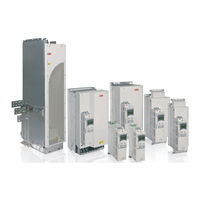
ABB ACQ810 Firmware Manual (376 pages)
Standard pump control program for drives
Brand:
ABB
| Category:
Control Unit
| Size: 7.04 MB
Table of Contents
List of Related Manuals
2
Table of Contents
5
About the Manual
11
What this Chapter Contains
11
Compatibility
11
Safety Instructions
11
Reader
11
Contents
12
Terms and Abbreviations
12
The ACQ810 Control Panel
15
What this Chapter Contains
15
Features
15
Installation
16
Mechanical Installation
16
Electrical Installation
16
Layout
17
Status Line
18
Operating Instructions
19
Basics of Operation
19
List of Tasks
20
Help and Panel Version - any Mode
21
Basic Operations - any Mode
22
Output Mode
23
Parameters
25
Assistants
32
Changed Parameters
33
Fault Logger
35
Time & Date
37
Parameter Backup
39
I/O Settings
47
Reference Edit
49
Drive Info
50
Parameter Change Log
51
Control Locations
53
What this Chapter Contains
53
Local Control Vs. External Control
54
Local Control
54
External Control
55
Program Features
57
What this Chapter Contains
57
Pump Control Features
58
PID Control
58
Sleep Function
59
Soft Pipefill
60
Autochange
61
Flow Calculation
62
Pump Cleaning
63
Protective Functions
64
Control Interfaces
65
Programmable Analog Inputs
65
Programmable Analog Outputs
65
Programmable Digital Inputs and Outputs
65
Programmable I/O Extensions
66
Programmable Relay Outputs
66
Fieldbus Control
66
Motor Control
68
Constant Speeds
68
Critical Speeds
68
Speed Controller Tuning
68
Scalar Motor Control
70
User-Definable Load Curve
71
User-Definable U/F Curve
72
Flux Braking
73
Application Control
74
Application Macros
74
Timers
74
DC Voltage Control
76
Overvoltage Control
76
Undervoltage Control
76
Voltage Control and Trip Limits
76
Safety and Protections
78
Emergency Stop
78
Thermal Motor Protection
78
Programmable Protection Functions
79
Automatic Fault Reset
80
Diagnostics
81
Energy Savings Calculator
81
Energy Consumption Monitoring
81
Signal Supervision
81
Maintenance Counters
82
Load Analyzer
82
Miscellaneous
84
Backup and Restore of Drive Contents
84
Data Storage Parameters
85
Drive-To-Drive Link
86
Application Macros
87
What this Chapter Contains
87
General
87
Factory Default Macro
88
Description and Typical Application
88
Default Settings
88
Default Control Connections
89
External Control Macro
90
Description and Typical Application
90
Default Settings
90
Default Control Connections
91
Hand/Auto Control Macro
92
Description and Typical Application
92
Default Settings
92
Default Control Connections
93
TRAD (Traditional Pump) Control Macro
94
Description and Typical Application
94
Default Settings
94
Default Control Connections
95
Application Examples
96
Level Control Macro
102
Description and Typical Application
102
Default Settings
103
Default Control Connections
104
Multipump Control Macro
105
Description and Typical Application
105
Default Settings
105
Default Control Connections
107
Pressure Sensor Connection Examples
108
Parameters
109
What this Chapter Contains
109
Terms and Abbreviations
109
Summary of Parameter Groups
110
Parameter Listing
112
Actual Values
112
O Values
113
Control Values
123
Appl Values
123
Pump Values
124
Drive Status
126
Alarms & Faults
131
System Info
134
Start/Stop/Dir
135
Start/Stop Mode
140
Operating Mode
141
Analogue Inputs
142
Digital I/O
148
Analogue Outputs
158
System
164
Speed Calculation
167
Limits
170
Speed Ref
172
Speed Ref Ramp
173
Speed Ctrl
176
Critical Speed
184
Constant Speeds
185
Process PID
187
Procact Sel
191
Setpoint Sel
193
Fault Functions
195
Motor Therm Prot
197
Automatic Reset
202
Supervision
202
User Load Curve
205
Process Variable
207
Timed Functions
214
Flux Ref
218
Motor Control
219
Maintenance
221
Energy Optimising
227
Voltage Ctrl
228
Data Storage
228
Fieldbus
229
FBA Settings
231
FBA Data in
232
FBA Data out
233
Panel Display
233
Embedded Modbus
234
Load Analyzer
238
Pump Logic
241
MF Communication
250
Pump Sleep
254
Pump Autochange
257
Level Control
262
Flow Calculation
267
Pump Protection
271
Pump Cleaning
278
Energy Monitoring
280
Ext IO Conf
281
Hw Configuration
281
User Motor Par
282
Start-Up Data
283
Additional Parameter Data
287
What this Chapter Contains
287
Terms and Abbreviations
287
Fieldbus Addresses
288
Pointer Parameter Format in Fieldbus Communication
288
32-Bit Integer Value Pointers
288
32-Bit Integer Bit Pointers
289
Parameter Groups 1
290
Parameter Groups 10
294
Fault Tracing
313
What this Chapter Contains
313
Safety
313
How to Reset
313
Fault History
314
Alarm Messages Generated by the Drive
314
Fault Messages Generated by the Drive
321
Control through the Embedded Fieldbus Interface
329
What this Chapter Contains
329
System Overview
330
Connecting the Fieldbus to the Drive
331
Setting up the Embedded Fieldbus Interface
332
Setting the Drive Control Parameters
334
Basics of the Embedded Fieldbus Interface
336
Control Word and Status Word
337
References
337
Actual Values
337
Data Inputs/Outputs
337
About the EFB Communication Profiles
338
ABB Drives Classic Profile and ABB Drives Enhanced Profile
339
Control Word for the ABB Drives Profiles
339
Status Word for the ABB Drives Profiles
341
State Transition Diagram for the ABB Drives Profiles
343
References for the ABB Drives Profiles
344
Actual Values for the ABB Drives Profiles
345
Modbus Register Addresses for the ABB Drives Classic Profile
346
Modbus Register Addresses for the ABB Drives Enhanced Profile
347
DCU 16-Bit Profile
348
Control and Status Words for the DCU 16-Bit Profile
348
Status Word for the DCU 16-Bit Profile
348
State Transition Diagram for the DCU 16-Bit Profile
348
References for the DCU 16-Bit Profile
348
Actual Signals for the DCU 16-Bit Profile
348
Modbus Register Addresses for the DCU 16-Bit Profile
349
DCU 32-Bit Profile
350
Control and Status Words for the DCU 32-Bit Profile
350
Status Word for the DCU 32-Bit Profile
350
State Transition Diagram for the DCU 32-Bit Profile
350
References for the DCU 32-Bit Profile
351
Modbus Register Addresses for the DCU 32-Bit Profile
353
Modbus Function Codes
354
Modbus Exception Codes
355
Control through a Fieldbus Adapter
357
What this Chapter Contains
357
System Overview
358
Setting up Communication through a Fieldbus Adapter Module
359
Drive Control Parameters
361
The Fieldbus Control Interface
362
The Control Word and the Status Word
363
Actual Values
363
FBA Communication Profile
363
Fieldbus References
364
State Diagram
365
Control Block Diagrams
367
What this Chapter Contains
367
Speed Feedback
368
Speed Reference Chain
369
Speed Error Handling
370
Torque Reference Modification, Operating Mode Selection
371
Process PID Control Setpoint and Actual Value Selection
372
Direct Torque Control
373
Further Information
375
Product and Service Inquiries
375
Product Training
375
Providing Feedback on ABB Drives Manuals
375
Document Library on the Internet
375
Advertisement
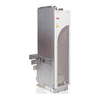
ABB ACQ810 Hardware Manual (134 pages)
Drive modules 200 to 400 kW, 250 to 600 hp
Brand:
ABB
| Category:
Control Unit
| Size: 10.21 MB
Table of Contents
List of Related Manuals
2
Table of Contents
5
1 Safety Instructions
11
What this Chapter Contains
11
Use of Warnings
11
Safety in Installation and Maintenance
12
Electrical Safety
12
Grounding
13
General Safety
14
Fiber Optic Cables
15
Printed Circuit Boards
15
Safe Start-Up and Operation
15
General Safety
15
2 Introduction to the Manual
17
What this Chapter Contains
17
Target Audience
17
Contents of the Manual
17
Related Manuals
18
Categorization by Option Code
18
Quick Installation, Commissioning and Operating Flowchart
18
Terms and Abbreviations
20
3 Operation Principle and Hardware Description
21
What this Chapter Contains
21
Product Overview
21
Layout
23
Alternative Output Busbar Configurations
25
Control Unit Variants
25
Component Placement
26
Power Connections and Control Interfaces
27
Cables for Connecting the Control Unit to the Drive Module and Control Panel
28
Circuit Boards
28
Type Designation Label
28
Type Designation Key
29
4 Planning the Cabinet Installation
31
What this Chapter Contains
31
Basic Requirements for the Cabinet
31
Planning the Layout of the Cabinet
32
Layout Examples, Door Closed
32
Layout Examples, Door Open
33
Arranging the Grounding Inside the Cabinet
34
Selecting Busbar Material and Preparation of the Joints
34
Tightening Torques
34
Planning the Fastening of the Cabinet
34
Planning the Cabinet Placement on a Cable Channel
35
Planning the Electro Magnetic Compatibility (EMC) of the Cabinet
35
Planning the Grounding of the Cable Shields at the Cabinet Lead-Through
37
Planning the Cooling
37
Preventing the Recirculation of Hot Air
39
Prevention the Air Recirculation Outside the Cabinet
39
Prevention the Air Recirculation Inside the Cabinet
39
Required Free Space Around the Drive Module
39
Free Space at Top with High Air Inlet Gratings in the Cabinet Door
40
Free Space at Top with Low Air Inlet Gratings in the Cabinet Door
40
Free Space at the Side and Front of the Drive Module
41
Other Installation Positions
41
Planning the Placement of the Control Panel
42
Planning the Use of Cubicle Heaters
42
5 Mechanical Installation
43
What this Chapter Contains
43
Safety
44
Checking the Installation Site
44
Required Tools
44
Moving and Unpacking the Unit
45
Checking the Delivery
45
Attaching the Warning Stickers
46
Fastening the Cable Lug Terminals to the Output Busbars
46
Fastening the Drive Module to the Cabinet Base
48
Installing the Drive Control Unit
49
Mounting through the Fastening Holes
49
Vertical DIN Rail Mounting
50
Horizontal DIN Rail Mounting
50
6 Planning the Electrical Installation
51
What this Chapter Contains
51
Selecting the Supply Disconnecting Device (Disconnecting Means)
51
European Union
52
Other Regions
52
Selecting and Dimensioning the Main Contactor
52
Protecting the Motor Insulation and Bearings
52
Checking the Compatibility of the Motor and Drive
52
Requirements Table
53
Explosion-Safe (EX) Motors
54
High-Output Motors and IP 23 Motors
55
HXR and AMA Motors
55
ABB Motors of Types Other than M2_, M3_, HX_ and am
55
Calculating the Rise Time and the Peak Line-To-Line Voltage
55
Sine Filters
56
Selecting the Power Cables
56
General Rules
56
Typical Power Cable Sizes
57
Typical Power Cable Sizes (US)
57
Alternative Power Cable Types
58
Motor Cable Shield
58
Additional US Requirements
58
Conduit
59
Armored Cable / Shielded Power Cable
59
Selecting the Control Cables
59
Shielding
59
Signals in Separate Cables
59
Signals Allowed to be Run in the same Cable
59
Relay Cable Type
60
Control Panel Cable Length and Type
60
Routing the Cables
60
Separate Control Cable Ducts
61
Continuous Motor Cable Shield or Enclosure for Equipment in the Motor Cable
61
Implementing Thermal Overload and Short-Circuit Protection
62
Protecting the Drive and Input Power Cable in Short-Circuits
62
Protecting the Motor and Motor Cable in Short-Circuits
62
Protecting the Drive and the Input Power and Motor Cables against Thermal Overload
62
Protecting the Motor against Thermal Overload
63
Protecting the Drive against Ground Faults
63
Residual Current Device Compatibility
63
Implementing the Emergency Stop Function
63
Implementing the Safe Torque off Function
64
Implementing the Power-Loss Ride-Through Function
65
Using Power Factor Compensation Capacitors with the Drive
65
Using a Contactor between the Drive and the Motor
65
Implementing a Bypass Connection
66
Protecting the Contacts of Relay Outputs
67
Connecting a Motor Temperature Sensor to the Drive I/O
68
Considering the PELV on Installation Sites above 2000 Meters (6562 Feet)
68
Example Circuit Diagram
69
7 Electrical Installation
71
What this Chapter Contains
71
Warnings
71
Checking the Insulation of the Assembly
71
Drive
71
Input Power Cable
71
Motor and Motor Cable
72
Connecting the Power Cables
73
Connection Diagram
73
Input Cable Connection Procedure
74
Removing the Protective Covering
74
Motor Cable Connection Procedure
75
DC Connection
76
Checking the Settings of the Cooling Fan Transformer
76
Removing the Cover Assembly
77
Fastening the Control Cable Clamp Plate
78
Grounding the Control Unit
78
Connecting the Control Unit to the Drive Module
79
Connecting the Control Cables
80
Default I/O Connection Diagram
81
Jumpers
82
External Power Supply for the JCU Control Unit (XPOW)
83
DI5 (XDI:5) as a Thermistor Input
83
Start Interlock (XDI:A)
84
Drive-To-Drive Link (XD2D)
84
Safe Torque off (XSTO)
85
Control Cable Connection Procedure
85
Routing the Control Cables
86
Connecting a PC
87
Installing Optional Modules
87
Mechanical Installation
87
Wiring the Modules
87
8 Installation Checklist
89
What this Chapter Contains
89
Mechanical Installation
89
Cabinet Construction
89
Instrumentation, Busbars and Cabling
90
Groundings and Protection
91
Labels, Switches, Fuses and Doors
91
Electrical Installation
91
Cooling and Driven Equipment
92
9 Start-Up
93
What this Chapter Contains
93
Start-Up Procedure
93
10 Fault Tracing
95
What this Chapter Contains
95
Leds
95
Warning and Fault Messages
95
11 Maintenance
97
What this Chapter Contains
97
Maintenance Intervals
97
Cabinet
98
Heatsink
98
Fan
98
Replacing the Cooling Fan of the Module
99
Replacing the Drive Module
100
Capacitors
102
Reforming the Capacitors
102
Replacing the Capacitor Pack
103
Memory Unit
104
12 Technical Data
105
What this Chapter Contains
105
Ratings
105
Derating
106
Ambient Temperature Derating
106
Altitude Derating
106
Fuses (IEC)
107
Calculation Example
107
Fuse Tables
109
Gg Fuses
109
Ultrarapid (Ar) Fuses
109
Quick Guide for Selecting between Gg and Ar Fuses
110
Fuses (UL)
110
UL Class T and L Fuses
111
Dimensions, Weights and Free Space Requirements
111
Losses, Cooling Data and Noise
112
IP22 Cabinet with no Extra Fan
112
IP54 Cabinet with an Extra Fan
112
Terminal and Lead-Through Data for the Power Cables
113
Terminal Data for the Control Cables
113
Electrical Power Network Specification
113
Motor Connection Data
113
Control Unit (JCU-21) Connection Data
114
Efficiency
116
Degree of Protection
116
Ambient Conditions
116
Materials
117
Applicable Standards
117
CE Marking
118
Compliance with the European Low Voltage Directive
118
Compliance with the European EMC Directive
118
Compliance with the European Machinery Directive
118
C-Tick" Marking
118
Compliance with the en 61800-3:2004
118
Definitions
118
Category C3
119
Category C4 (+0E200)
119
UL Marking
120
UL Checklist
120
CSA Marking
120
Patent Protection in the USA
120
13 Dimension Drawings
121
What this Chapter Contains
121
Frame Without Pedestal (MM)
122
Frame with Busbars on the Left Side (MM)
123
Drive Control Unit (JCU)
124
Package
125
Dimension Drawings (USA)
126
Frame Without Pedestal (Inches)
126
Frame with Busbars on the Left Side (Inches)
127
14 Example Circuit Diagrams
129
What this Chapter Contains
129
Example Circuit Diagram
130
15 Du/Dt Filters and Sine Filters
131
What this Chapter Contains
131
Du/Dt Filters
131
When Is Du/Dt Filter Needed
131
Selection Table
131
Description, Installation and Technical Data of the FOCH Filters
131
Sine Filters
132
Further Information
133
Product and Service Inquiries
133
Product Training
133
Providing Feedback on ABB Drives Manuals
133
Document Library on the Internet
133
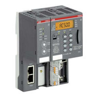
ABB ACQ810 Quick Start Manual (48 pages)
PLC and drives integration using Modbus RTU
Brand:
ABB
| Category:
Controller
| Size: 2.6 MB
Table of Contents
Table of Contents
2
Introduction
4
Safety Instructions
4
Limitations
4
Fieldbus Grounding
6
Fieldbus Shield
6
End Termination
6
Pull Up/Pull down Resistors
6
Drives with Embedded Fieldbus
7
Fieldbus Modules for ABB Drives
8
Common Recommendations
8
ABB Cable TK505
9
AC500 COM1 - Master at the Bus Line End
11
AC500 COM2 - Master at the Bus Line End
11
AC500-Eco COM1 - Master at the Bus Line End
11
AC500-Eco COM2 - Master at the Bus Line End
12
Drive Configuration
13
Starting up ACS310 Drives with Embedded Modbus RTU
14
Starting up ACS355 Drives with FMBA-01 Modbus RTU Adapter
15
Starting up ACS800 Drives with RMBA-01 Modbus RTU Adapter
17
Starting up ACS850, ACQ810 Drives with Embedded Modbus RTU
18
Starting up ACS880 Drives with FSCA-01 Modbus RTU Adapter
19
Starting up ACSM1 Drives with FSCA-01 Modbus RTU Adapter
20
Install Drives Library
21
Control Builder Plus for PLC and Drives
22
Hardware Configuration
22
IP Configuration of CPU (for Ethernet Connection between PC and PLC)
24
Codesys
25
CODESYS Tabs
25
Library Manager
26
PLC Logic
27
Download Program to PLC
32
Create Boot Project
33
Test the Program
34
Read and Write more Data between PLC and Drive (Optional)
36
Visualizations
43
Add more Drives (Optional)
46
Actualization Rate
47
Other Useful Documentation
47
Revision
47
Advertisement
Advertisement
Related Products
ABB ACQ580-04
ABB ACH550 series
ABB ACSM1-04 Series
ABB ACSM1-04Lx
ABB ACS880-204LC
ABB ACS880-04F
ABB ACS104LC
ABB ACSM1-204
ABB ACH580-04
ABB ACS880-304 +A003 Series
ABB Categories
Industrial Equipment
Controller
Measuring Instruments
Battery Charger
DC Drives
More ABB Manuals
Login
Sign In
OR
Sign in with Facebook
Sign in with Google
Upload manual
Upload from disk
Upload from URL