Sign In
Upload
Manuals
Brands
ABB Manuals
Control Unit
ACQ580-04
ABB ACQ580-04 Manuals
Manuals and User Guides for ABB ACQ580-04. We have
9
ABB ACQ580-04 manuals available for free PDF download: Hardware Manual, Quick Installation Manual, User Manual, Manual
ABB ACQ580-04 Hardware Manual (234 pages)
drive modules
Brand:
ABB
| Category:
DC Drives
| Size: 29 MB
Table of Contents
Table of Contents
5
Table of Contents
7
Safety Instructions
15
Contents of this Chapter
15
Use of Warnings and Notes
15
General Safety in Installation, Start-Up and Maintenance
16
Electrical Safety in Installation, Start-Up and Maintenance
18
Electrical Safety Precautions
18
Additional Instructions and Notes
19
Optical Components
20
Printed Circuit Boards
20
Grounding
20
General Safety in Operation
21
Additional Instructions for Permanent Magnet Motor Drives
22
Safety in Installation, Start-Up, Maintenance
22
Safety in Operation
22
Introduction to the Manual
23
Contents of this Chapter
23
Applicability
23
Target Audience
23
Purpose of the Manual
23
Categorization by Frame Size and Option Code
23
Terms and Abbreviations
24
Quick Installation, Commissioning and Operating Flowchart
25
Related Documents
26
Operation Principle and Hardware Description
27
Contents of this Chapter
27
Product Overview
28
Layout
29
Standard Drive Module Configuration
29
Drive Module Configuration with Option +B051
30
Control Panel
32
Overview of Power and Control Connections
33
Type Designation Label
34
Type Designation Key
35
Basic Code
35
Option Codes
35
Ordering Codes
36
Generic Cabinet Planning Instructions
37
Contents of this Chapter
37
Limitation of Liability
37
Cabinet Construction
37
Disposition of the Devices
37
Grounding of Mounting Structures
38
Busbar Material and Joints
38
Shrouds
38
Tightening Torques
38
Electrical Connections
38
Mechanical Connections
38
Insulation Supports
39
Cable Lugs
39
Cooling and Degrees of Protection
39
Planning the Cooling
39
Air Inlets and Outlets
39
Preventing the Recirculation of Hot Air
40
EMC Requirements
41
Attaching the Cabinet
43
Cabinet Placement on a Cable Channel
43
Heaters
43
Mounting the Control Panel on the Cabinet Door
44
Guidelines for Planning the Mechanical Installation
45
Contents of this Chapter
45
Installation Positions of the Drive Module
45
Planning the Layout
46
Layout Example, Door Closed
46
Layout Example, Door Open (Standard Drive Module Configuration)
47
Layout Example, Door Open (Option +B051)
49
Planning the Cooling of the ACQ580-04
50
Standard Drive Module Configuration
51
Drive Module with Option +B051
52
Other Installation Positions than Vertical
53
Free Space Requirements
53
Free Space at the Top of the Drive Module
53
Free Space Around the Drive Module
53
Mechanical Installation
55
Contents of this Chapter
55
Examining the Installation Site
55
Moving and Unpacking the Unit
56
Lifting the Drive Module
60
Examining the Delivery
60
Installation Alternatives
60
Input Power Cable Connection Terminals (Option +H370) and Ground Busbar Assembly
61
Drive Module Without Output Cable Connection Terminals (Option +0H371)
61
Drive Module Without Pedestal (Option +0H354)
61
Attaching the Drive Module to a Mounting Plate or Wall
61
Alternatives for Grounding the Drive Module
62
Installing the Bottom Grille for IP20 Degree Protection
63
Removing the Protective Covering from the Drive Module Air Outlet
64
Installing External Control Unit (Option +P906)
64
Guidelines for Planning the Electrical Installation
65
Contents of this Chapter
65
Limitation of Liability
65
Selecting the Main Supply Disconnecting Device
65
European Union
65
North America
66
Other Regions
66
Selecting the Main Contactor
66
Examining the Compatibility of the Motor and Drive
66
Protecting the Motor Insulation and Bearings
66
Requirements Table
67
Availability of Du/Dt Filter and Common Mode Filter by Drive Type
69
Additional Requirements for Explosion-Safe (EX) Motors
69
And am
69
Additional Requirements for ABB High-Output and IP23 Motors
69
Additional Requirements for Non-ABB High-Output and IP23 Motors
69
Additional Data for Calculating the Rise Time and the Peak Line-To-Line Voltage
70
Selecting the Power Cables
71
General Guidelines
71
Typical Power Cable Sizes
72
Power Cable Types
72
Preferred Power Cable Types
72
Alternate Power Cable Types
73
Not Allowed Power Cable Types
74
Additional Guidelines, North America
74
Metal Conduit
75
Power Cable Shield
75
Selecting the Control Cables
75
Shielding
75
Signals in Separate Cables
76
Signals that Can be Run in the same Cable
76
Relay Cable
76
Control Panel to Drive Cable
76
PC Tool Cable
76
Routing the Cables
76
General Guidelines - IEC
76
General Guidelines - North America
77
Continuous Motor Cable Shield/Conduit or Enclosure for Equipment on the Motor Cable
78
Separate Control Cable Ducts
78
Implementing Motor and Motor Cable Short-Circuit and Thermal Overload Protection
79
Protecting the Motor and Motor Cable in Short-Circuits
79
Protecting the Motor Cables against Thermal Overload
79
Protecting the Motor against Thermal Overload
79
Protecting the Motor against Overload Without Thermal Model or Temperature Sensors
79
Protecting the Drive and Input Power Cable in Short-Circuits
80
Circuit Breakers
80
Tested Circuit Breakers
80
Protecting the Drive against Ground Faults
80
Residual Current Device Compatibility
80
Implementing the Emergency Stop Function
81
Implementing the Safe Torque off Function
81
Implementing the Undervoltage Control (Power-Loss Ride-Through)
81
Using Power Factor Compensation Capacitors with the Drive
81
Using a Safety Switch between the Drive and the Motor
82
Implementing an ATEX-Certified Motor Thermal Protection
82
Controlling a Contactor between Drive and Motor
82
Implementing a Bypass Connection
83
Example Bypass Connection
84
Switching the Motor Power Supply from Drive to Direct-On-Line
85
Switching the Motor Power Supply from Direct-On-Line to Drive
85
Protecting the Contacts of Relay Outputs
85
Implementing a Motor Temperature Sensor Connection
86
Connecting Motor Temperature Sensor to the Drive Via an Option Module
86
Electrical Installation
89
Contents of this Chapter
89
Safety
89
Grounding the Motor Cable Shield at the Motor End
89
Measuring the Insulation
90
Measuring the Insulation of the Drive
90
Measuring the Insulation of the Input Power Cable
90
Measuring the Insulation of the Motor and Motor Cable
90
Grounding System Compatibility Check - IEC, Not North America
90
EMC Filter Compatibility
91
Ground-To-Phase Varistor Compatibility
91
Grounding System Compatibility Check - North America
91
Connecting the Power Cables
92
Power Cable Connection Diagram
92
Preparing the Cable Ends - Symmetrical Shielded Cables
94
Power Cable Connection Process
94
DC Connection
94
Connecting the Control Cables
95
Connecting a Control Panel
96
Connecting a PC
97
Connecting a Remote Panel, or Chaining One Panel to Several Drives
97
Installing Option Modules
97
Option Slot 2 (I/O Extension Modules)
98
Option Slot 1 (Fieldbus Adapter Modules)
99
Wiring the Optional Modules
99
Installation Example of Drive Module with IP20 Shrouds (Option +B051)
101
Contents of this Chapter
101
Safety
101
Required Parts
102
Required Tools
102
Overall Flowchart of the Installation Process
103
Installing the Drive Module into a Cabinet
103
Connecting the Power Cables and Installing the Shrouds
104
Installing the Roof and Door (Rittal Parts)
105
Miscellaneous
106
Input Power Cable Entry from Top
106
Attaching the Drive Module to a Mounting Plate
106
Control Unit
107
Contents of this Chapter
107
Layout
108
Default I/O Connection Diagram
109
Switches
110
Additional Information on I/O Connections
110
PNP Configuration for Digital Inputs (X2 & X3)
110
NPN Configuration for Digital Inputs (X2 & X3)
111
Connection for Obtaining 0
111
Connection Examples of Two-Wire and Three-Wire Sensors to Analog Input (AI2)
112
DI5 as Frequency Input
112
DI6 as PTC Input
112
AI1 and AI2 as Pt100, Pt1000, Ni1000, KTY83 and KTY84 Sensor Inputs (X1)
113
Safe Torque off (X4)
113
Technical Data
114
Installation Checklist
119
Contents of this Chapter
119
Checklist
119
Start-Up
121
Contents of this Chapter
121
Start-Up Procedure
121
Fault Tracing
123
Contents of this Chapter
123
Leds
123
Warning and Fault Messages
123
Maintenance
125
Contents of this Chapter
125
Maintenance Intervals
125
Cabinet
126
Cleaning the Interior of the Cabinet
126
Heatsink
127
Cleaning the Interior of the Heatsink
127
Fans
129
Replacing the Circuit Board Compartment Cooling Fans
129
Replacing the Main Cooling Fans
130
Replacing the Drive Module
131
Capacitors
133
Reforming the Capacitors
133
Control Panel
133
Technical Data
135
Contents of this Chapter
135
Electrical Ratings
136
IEC Ratings
136
UL (NEC) Ratings
136
Definitions
137
Output Derating
137
When Is Derating Necessary
137
Surrounding Air Temperature Derating
138
Altitude Derating
139
Switching Frequency Derating
139
Fuses (IEC)
140
Fuses (UL)
141
Circuit Breakers (IEC)
142
Dimensions, Weights and Free Space Requirements
142
Losses, Cooling Data and Noise
144
Terminal and Entry Data for the Power Cables
144
Drive Modules Without Output Cable Connection Terminals (+0H371) and with a Common Mode Filter (+E208)
144
Typical Power Cable Sizes
145
Terminal Data for the Control Cables
146
Electrical Power Network Specification
146
Motor Connection Data
146
DC Connection Data
147
Control Panel Type
147
Control Unit Data
147
Efficiency
147
Protection Classes
147
Ambient Conditions
148
Materials
148
Applicable Standards
149
Markings
149
EMC Compliance (IEC/EN 61800-3:2004 + A2012)
150
Definitions
150
Category C3
151
Category C4
151
Compliance with the European Machinery Directive
152
UL and CSA Checklist
152
Design Lifetime Expectancy
153
Disclaimers
153
Generic Disclaimer
153
Cybersecurity Disclaimer
153
Dimension Drawings
155
Contents of this Chapter
155
R10 Standard Configuration
156
R10 with +E208+0H354+H356+H370+0H371
157
R10 with Option +B051
158
R10 with Option +E208 +H356 +P906
159
R10 with Option +E208+0H371+H356+0H354+H370+P906
160
R10 with Option +B051 +P906
161
R11 Standard Configuration
162
R11 with Option +E208+0H371+H356+0H354+H370
163
R11 with Option +B051
164
R11 with Option +E208 +H356 +P906
165
R11 with Option +E208+0H371+H356+0H354+H370+P906
166
R11 with Option +B051 +P906
167
Air Baffles for the Drive Module with Option +B051
168
Example Circuit Diagram
169
Contents of this Chapter
169
The Safe Torque off Function
171
Contents of this Chapter
171
Description
171
Compliance with the European Machinery Directive
172
Wiring
173
Connection Principle
173
Single ACQ580-04 Drive, Internal Power Supply
173
Single ACQ580-04 Drive, External Power Supply
173
Wiring Examples
174
Single ACQ580-04 Drive, Internal Power Supply
174
Single ACQ580-04 Drive, External Power Supply
174
Multiple ACQ580-04 Drives, Internal Power Supply
175
Multiple ACQ580-04 Drives, External Power Supply
176
Activation Switch
176
Cable Types and Lengths
177
Grounding of Protective Shields
177
Operation Principle
178
Start-Up Including Acceptance Test
179
Competence
179
Acceptance Test Reports
179
Acceptance Test Procedure
179
Use
181
Maintenance
182
Competence
182
Fault Tracing
183
Safety Data
184
Abbreviations
184
TÜV Certificate
185
Declaration of Conformity
186
External Control Unit (Option +P906)
187
Contents of this Chapter
187
Product Overview
187
Layout
188
Cables
188
Unpacking the Delivery
189
Installing the Control Unit
190
Installation Procedure
190
Optical Components
190
Connecting the Control Unit to the Drive Module
195
Maintenance
197
Dimension Drawing
198
CHDI-01 115/230 V Digital Input Extension Module
199
Contents of this Chapter
199
Product Overview
199
Layout and Connection Examples
200
Mechanical Installation
201
Necessary Tools
201
Unpacking and Examining the Delivery
201
Installing the Module
201
Electrical Installation
201
Wiring
201
Start-Up
201
Setting the Parameters
201
Parameter Setting Example for Relay Output
202
Fault and Warning Messages
202
Technical Data
202
Dimension Drawing
203
CMOD-01 Multifunction Extension Module (External 24 V AC/DC and Digital I/O)
205
Contents of this Chapter
205
Product Overview
205
Layout and Example Connections
206
Mechanical Installation
207
Necessary Tools
207
Unpacking and Examining the Delivery
207
Installing the Module
207
Electrical Installation
207
Wiring
207
Start-Up
208
Setting the Parameters
208
Diagnostics
209
Faults and Warning Messages
209
Leds
209
Technical Data
209
Dimension Drawing
210
CMOD-02 Multifunction Extension Module (External 24 V AC/DC and Isolated PTC Interface)
211
Contents of this Chapter
211
Product Overview
211
Layout and Example Connections
212
Mechanical Installation
212
Necessary Tools
212
Unpacking and Examining the Delivery
213
Installing the Module
213
Electrical Installation
213
Necessary Tools and Instructions
213
Wiring
213
Start-Up
213
Setting the Parameters
213
Diagnostics
214
Faults and Warning Messages
214
Leds
214
Technical Data
214
Dimension Drawing
215
Filters
217
Contents of this Chapter
217
When Is a Du/Dt Filter Necessary
217
Selection Table
217
Ordering Codes
217
Description, Installation and Technical Data of the FOCH Filters
217
Ground-To-Phase Varistor Disconnecting Instructions - IEC, Not North America
219
Contents of this Chapter
219
Identifying the Grounding System of the Electrical Power Network
219
When to Disconnect Ground-To-Phase Varistor: TN-S, IT, Corner-Grounded Delta and MID-Point-Grounded Delta Systems
220
Guidelines for Installing the Drive to a TT System
222
Disconnecting Instruction - IEC, Not North America
222
Connecting EMC Filter and Ground-To-Phase Varistor - North America
223
Contents of this Chapter
223
Identifying the Grounding System of the Electrical Power Network
223
When You Can Connect the EMC Filter and Ground-To-Phase Varistor: TN-S, IT, Corner-Grounded Delta and MID-Point-Grounded Delta Systems
224
Connecting EMC Filter - North America
225
Connecting Ground-To-Phase Varistor - North America
225
Step-By-Step Drawings for an Installation Example of a Drive Module with the +B051 Option in a Rittal VX25 600 MM Wide Enclosure
227
Further Information
233
Advertisement
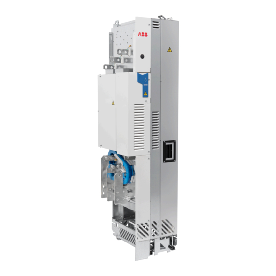
ABB ACQ580-04 Hardware Manual (180 pages)
drive modules
Brand:
ABB
| Category:
Control Unit
| Size: 21 MB
Table of Contents
List of Related Manuals
2
Table of Contents
5
Safety Instructions
13
Contents of this Chapter
13
Use of Warnings and Notes
13
General Safety in Installation, Start-Up and Maintenance
14
Electrical Safety in Installation, Start-Up and Maintenance
16
Precautions before Electrical Work
16
Additional Instructions and Notes
17
Grounding
18
Additional Instructions for Permanent Magnet Motor Drives
19
Safety in Installation, Start-Up and Maintenance
19
Introduction to the Manual
21
Contents of this Chapter
21
Target Audience
21
Contents of the Manual
22
Categorization by Frame Size and Option Code
23
Quick Installation, Commissioning and Operating Flowchart
23
Terms and Abbreviations
25
Operation Principle and Hardware Description
27
Contents of this Chapter
27
Product Overview
27
Layout
28
Drive Module Configuration with Option +B051
29
Control Panel
31
Overview of Power and Control Connections
32
Control Connection Terminals
33
Type Designation Label
34
Type Designation Key
34
Guidelines for Planning the Cabinet Installation
37
Contents of this Chapter
37
Limitation of Liability
37
Installation Positions of the Drive Module
37
Basic Requirements for the Cabinet
37
Planning the Layout of the Cabinet
38
Layout Example, Door Closed
38
Layout Example, Door Open (Standard Drive Module Configuration)
39
Layout Example, Door Open (Option +B051)
40
Arranging the Grounding Inside the Cabinet
41
Selecting the Busbar Material and Preparation of the Joints
41
Tightening Torques
41
Planning the Fastening of the Cabinet
41
Planning the Cabinet Placement on a Cable Channel
42
Planning the Electromagnetic Compatibility (EMC) of the Cabinet
42
Planning the Cooling
44
Preventing the Recirculation of Hot Air
45
Standard Drive Module Configuration
46
Drive Module with Option +B051
48
Required Free Space
49
Free Space at the Top of the Drive Module
49
Free Space Around the Drive Module
49
Other Installation Positions
49
Drive Module on Its Back
49
Planning the Placement of the Control Panel
50
Planning the Use of Cubicle Heaters
50
Arc Welding
50
Guidelines for Planning the Electrical Installation
51
Contents of this Chapter
51
Limitation of Liability
51
Selecting the Supply Disconnecting Device
52
European Union
52
Other Regions
52
Selecting the Main Contactor
52
Examining the Compatibility of the Motor and Drive
52
Protecting the Motor Insulation and Bearings
52
Requirements Table
53
And am
54
Additional Requirements for ABB High-Output and IP23 Motors
54
Additional Requirements for Non-ABB High-Output and IP23 Motors
54
Additional Data for Calculating the Rise Time and the Peak Line-To-Line Voltage
55
Additional Note for Common Mode Filters
55
Selecting the Power Cables
55
General Rules
55
Sufficient Conductivity of the Protective Conductor
56
Typical Power Cable Sizes
57
Alternative Power Cable Types
58
Recommended Power Cable Types
58
Power Cable Types for Restricted Use
58
Not Allowed Power Cable Types
58
Motor Cable Shield
58
Selecting the Control Cables
59
Shielding
59
Signals in Separate Cables
59
Signals Allowed to be Run in the same Cable
59
Relay Cable Type
59
Control Panel Cable Length and Type
59
Routing the Cables
60
Separate Control Cable Ducts
60
Continuous Motor Cable Shield or Enclosure for Equipment in the Motor Cable
61
Implementing Thermal Overload and Short-Circuit Protection
61
Protecting the Drive and Input Power Cable in Short-Circuits
61
Protecting the Motor and Motor Cable in Short-Circuits
61
Protecting the Drive and the Input Power and Motor Cables against Thermal Overload
62
Protecting the Motor against Thermal Overload
62
Protecting the Drive against Ground Faults
62
Residual Current Device Compatibility
62
Implementing the Emergency Stop Function
63
Implementing the Safe Torque off Function
63
Implementing the Power Loss Ride-Through Function
63
Using Power Factor Compensation Capacitors with the Drive
63
Implementing a Safety Switch between the Drive and the Motor
63
Using a Contactor between the Drive and the Motor
64
Implementing a Bypass Connection
64
Example Bypass Connection
65
Switching the Motor Power Supply from Drive to Direct-On-Line
65
Switching the Motor Power Supply from Direct-On-Line to Drive
66
Protecting the Contacts of Relay Outputs
66
Connecting a Motor Temperature Sensor to the Drive I/O
67
Example Circuit Diagram
67
Installation Instructions
69
Contents of this Chapter
69
Safety
69
Checking the Installation Site
69
Moving and Unpacking the Unit
70
Checking the Delivery
74
Installing the Motor Cable at the Motor End
74
Checking the Insulation of the Assembly
75
Drive
75
Input Cable
75
Motor and Motor Cable
75
Installation Alternatives
75
Standard Drive Module Configuration and Option +B051
75
Optional Input Power Cable Connection Terminals and Ground Busbar Assembly (+H370)
75
Drive Module Without Output Cable Connection Terminals (Option +0H371)
76
Drive Module Without Pedestal (Option +0H354)
76
Attaching the Drive Module to a Mounting Plate or Wall
77
Alternatives for Grounding the Drive Module
77
Installing the Bottom Grille (for IP20 Degree Protection)
78
Connecting the Power Cables
79
Connection Diagram
79
Power Cable Connection Procedure
80
DC Connection
81
Connecting the Control Cables
82
Default I/O Connection Diagram (ABB Standard Macro)
84
Switches
85
PNP Configuration for Digital Inputs (X2 & X3))
85
NPN Configuration for Digital Inputs (X2 & X3)
86
Connection for Obtaining 0
86
Connection Examples of Two-Wire and Three-Wire Sensors to Analog Input (AI2)
87
DI6 as Frequency Input
87
DI6 as PTC Input
87
AI1 and AI2 as Pt100, Pt1000, Ni1000, KTY83 and KTY84 Sensor Inputs (X1)
88
Safe Torque off (X4)
88
Connecting a Control Panel
88
Installing Option Modules
89
Option Slot 2 (I/O Extension Modules)
89
Option Slot 1 (Fieldbus Adapter Modules)
89
Wiring the Optional Modules
89
Connecting a PC
90
Installation Example of Drive Module with IP20 Shrouds (Option +B051)
91
Contents of this Chapter
91
Limitation of Liability
91
Safety
91
Required Parts
92
Required Tools
92
Overall Flowchart of the Installation Process
92
Installing the Drive Module into a Cabinet
93
Connecting the Power Cables and Installing the Shrouds
93
Installing the Roof and Door
95
Miscellaneous
96
Input Power Cable Lead-Through from Top
96
Attaching the Drive Module to a Mounting Plate
96
IP20 Shrouds
96
Installation Checklist
97
Contents of this Chapter
97
Start-Up
101
Contents of this Chapter
101
Start-Up Procedure
101
Fault Tracing
103
Contents of this Chapter
103
Warning and Fault Messages
103
Maintenance
105
Contents of this Chapter
105
Maintenance Intervals
105
Descriptions of Symbols
106
Recommended Annual Maintenance Actions by the User
106
Recommended Maintenance Intervals after Start-Up
106
Cabinet
106
Cleaning the Interior of the Cabinet
106
Heatsink
107
Cleaning the Interior of the Heatsink
107
Fans
108
Replacing the Circuit Board Compartment Cooling Fan
108
Replacing the Main Cooling Fans
109
Replacing the Drive Module
110
Capacitors
111
Reforming the Capacitors
111
Control Panel
112
Cleaning the Control Panel
112
Replacing the Battery in the Assistant Control Panel
112
Technical Data
115
Contents of this Chapter
115
Ratings
115
IEC Ratings
115
NEMA Ratings
116
Output Derating
116
Ambient Temperature Derating
117
Altitude Derating
117
Deratings for Special Settings in the Drive Control Program
117
Fuses (IEC)
118
Ultrarapid (Ar) Fuses
118
Fuses (UL)
118
Dimensions, Weights and Free Space Requirements
119
Losses, Cooling Data and Noise
119
Terminal and Lead-Through Data for the Power Cables
119
Drive Modules Without Output Cable Connection Terminals (+0H371) and with a Common Mode Filter (+E208)
119
Terminal Data for the Control Cables
119
Electrical Power Network Specification
120
Motor Connection Data
120
DC Connection Data
120
Control Unit (CCU-24) Connection Data
120
Control Panel Type
122
Efficiency
122
Degree of Protection
122
Ambient Conditions
123
CE Marking
124
Compliance with the European Low Voltage Directive
124
Materials
124
Applicable Standards
124
Compliance with the European EMC Directive
125
Compliance with the European Rohs Directive
125
Compliance with the European Machinery Directive
125
Compliance with en 61800-3:2004
125
Definitions
125
Category C3
126
Category C4
126
UL Marking
127
China Rohs Marking
127
RCM Marking
127
WEEE Marking
128
EAC (Eurasian Conformity) Marking
128
Cybersecurity Disclaimer
128
Disclaimer
128
Dimension Drawings
129
Contents of this Chapter
129
R10 Standard Configuration
130
R10 with Options +E208+0H354+H356+0H370+0H371
131
R10 with Option +B051
132
R11 Standard Configuration
133
R11 with Options +E208+0H354+H356+0H370+0H371
134
R11 with Option +B051
135
Air Baffles for the Drive Module with Option +B051
136
Example Circuit Diagram 137
137
Contents of this Chapter
137
Example Circuit Diagram
138
Safe Torque off Function
139
Contents of this Chapter
139
Description
139
Compliance with the European Machinery Directive
140
Wiring
140
Activation Switch
140
Cable Types and Lengths
141
Grounding of Protective Shields
141
Single Drive (Internal Power Supply)
141
Single Drive (External +24 V DC Power Supply)
142
Dual-Channel Connection
142
Single-Channel Connection
143
Wiring Examples
143
Multiple Drives (Internal Power Supply)
145
Multiple Drives (External Power Supply)
146
Operation Principle
147
Start-Up Including Acceptance Test
147
Competence
147
Acceptance Test Reports
147
Acceptance Test Procedure
147
Use
148
Maintenance
149
Competence
150
Fault Tracing
150
Safety Data
150
Abbreviations
151
Declaration of Conformity
152
Optional I/O Extension Modules
153
Contents of this Chapter
153
CHDI-01 115/230 V Digital Input Extension Module
153
Safety Instructions
153
Hardware Description
153
Product Overview
153
Layout
154
Mechanical Installation
154
Necessary Tools and Instructions
154
Unpacking and Checking the Delivery
154
Installing the Module
154
Electrical Installation
155
Warnings
155
Necessary Tools and Instructions
155
Terminal Designations
155
General Cabling Instructions
155
Wiring
155
Start-Up
156
Setting the Parameters
156
Diagnostics
156
Faults and Warning Messages
156
Leds
157
Technical Data
157
Dimension Drawing
157
Isolation Areas
158
CMOD-01 Multifunction Extension Module (External 24 V AC/DC and Digital I/O)
159
Safety Instructions
159
Hardware Description
159
Product Overview
159
Layout
160
Mechanical Installation
160
Necessary Tools and Instructions
160
Unpacking and Checking the Delivery
160
Installing the Module
160
Electrical Installation
161
Warnings
161
Necessary Tools and Instructions
161
Terminal Designations
161
General Cabling Instructions
161
Wiring
161
Start-Up
163
Setting the Parameters
163
Diagnostics
163
Faults and Warning Messages
163
Leds
164
Technical Data
164
Dimension Drawing
164
CMOD-02 Multifunction Extension Module (External 24 V AC/DC and Isolated PTC Interface)
166
Safety Instructions
166
Hardware Description
166
Product Overview
166
Layout
167
Mechanical Installation
167
Necessary Tools and Instructions
167
Unpacking and Checking the Delivery
167
Installing the Module
167
Electrical Installation
168
Warnings
168
Necessary Tools and Instructions
168
Terminal Designations
168
General Cabling Instructions
168
Wiring
168
Start-Up
169
Setting the Parameters
169
Diagnostics
170
Faults and Warning Messages
170
Leds
170
Technical Data
170
CPTC-02 ATEX-Certified Thermistor Protection Module, (External 24 V AC/DC and Isolated PTC Interface)
172
Du/Dt Filters
173
Contents of this Chapter
173
When Is Du/Dt Filter Needed
173
Selection Table
173
Ordering Codes
173
Description, Installation and Technical Data of the FOCH Filters
173
Further Information
179
Product and Service Inquiries
179
Product Training
179
Providing Feedback on ABB Manuals
179
Document Library on the Internet
179
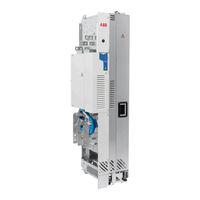
ABB ACQ580-04 Quick Installation Manual (66 pages)
drive modules
Brand:
ABB
| Category:
Industrial Equipment
| Size: 55 MB
Advertisement
ABB ACQ580-04 Quick Installation Manual (60 pages)
Drive modules
Brand:
ABB
| Category:
Control Unit
| Size: 4 MB
ABB ACQ580-04 Quick Installation Manual (28 pages)
R10 and R11 drives for water
Brand:
ABB
| Category:
DC Drives
| Size: 12 MB
Table of Contents
Table of Contents
3
Quick Installation Guide
5
Contents of this Guide
5
Obey the Safety Instructions
5
Select the Power Cables
6
Ensure the Cooling and Fuses (UL)
6
Protect the Drive and Input Power Cables
6
Install the Drive Module into a Cabinet
6
Check the Insulation of the Input and Motor Cables and the Motor
7
Connect the Power Cables (and Install the Shrouds for Option +B051)
8
Install the Air Baffles
9
Connect the Control Cables
9
Default I/O Connections
10
UL Checklist
11
ABB ACQ580-04 User Manual (22 pages)
ABB LV AC DRIVE PIHF Harmonic Filters
Brand:
ABB
| Category:
DC Drives
| Size: 0 MB
Table of Contents
Table of Contents
3
1 Manual Introduction
5
2 Safety Instructions
5
Contents
5
Safety of Installation and Maintenance
5
3 Guide on Installation and Debugging of Filters
7
Contents
7
Product Overview
7
Mechanical Installation
11
Electrical Connection
12
Model Information
14
Technical Data
16
Further Information
21
Product and Service Inquiries
21
Product Training
21
Providing Feedback on ABB Drives Manuals
21
Document Library on the Internet
21
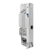
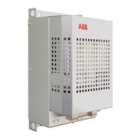
ABB ACQ580-04 Quick Installation Manual (26 pages)
drive modules
Brand:
ABB
| Category:
Industrial Equipment
| Size: 5 MB
Table of Contents
Contents of this Guide
9
Obey the Safety Instructions
9
Connect the Control Cables
13
Default I/O Connections
14
Safe Torque off (Sto)
15
Technical Data
15
EN - Technical Data
19
Dimensions, Weights and Free Space Requirements
20
Ambient Conditions
20
Declarations of Conformity
20
ABB ACQ580-04 Manual (16 pages)
Converter modules with electrolytic DC capacitors in the DC link
Brand:
ABB
| Category:
Control Unit
| Size: 0 MB
Table of Contents
Table of Contents
3
1 Introduction
5
Contents of this Chapter
5
Applicability
5
ABB Low Voltage AC Drives
5
ABB Wind Turbine Converters
6
ABB Solar Inverters
6
Target Audience
6
Purpose of the Manual
6
Safety Instructions
6
2 Reforming the Capacitors
9
Contents of this Chapter
9
Overview of the Reforming
9
Reforming Time
9
Checking the Converter Age
10
Reforming with Power on for 30 Minutes
11
Reforming with External DC Power Supply
11
Reforming with External Diode Bridge
13
Further Information
15
ABB ACQ580-04 Quick Installation Manual (20 pages)
Brand:
ABB
| Category:
Industrial Equipment
| Size: 5 MB
Advertisement
Related Products
ABB ACQ810
ABB ACL30-04-06A0-4
ABB ACS880-04F
ABB ACS811
ABB ACS804
ABB AC500 PLC
ABB ACP510-505A-4
ABB ACP510-650A-4
ABB ACP510-725A-4
ABB ACP510-820A-4
ABB Categories
Industrial Equipment
Controller
Measuring Instruments
Battery Charger
DC Drives
More ABB Manuals
Login
Sign In
OR
Sign in with Facebook
Sign in with Google
Upload manual
Upload from disk
Upload from URL