Sign In
Upload
Manuals
Brands
Aaeon Manuals
Motherboard
GENE-APL5
Aaeon GENE-APL5 Manuals
Manuals and User Guides for Aaeon GENE-APL5. We have
2
Aaeon GENE-APL5 manuals available for free PDF download: User Manual
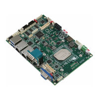
Aaeon GENE-APL5 User Manual (120 pages)
3.5" Subcompact Board
Brand:
Aaeon
| Category:
Motherboard
| Size: 4 MB
Table of Contents
Copyright Notice
2
Table of Contents
11
Chapter 1 - Product Specifications
15
Specifications
16
Chapter 2 - Hardware Information
19
Dimensions
20
Dimensions (Optional HDMI SKU)
22
Jumpers and Connectors
24
Jumpers and Connectors (Optional HDMI SKU)
26
Block Diagram
28
List of Jumpers
29
LVDS Port 1 Backlight Inverter VCC Selection (JP1)
30
LVDS Port 1 Operating VDD Selection (JP1)
30
LVDS Port 1 Backlight Lightness Control Mode Selection (JP2)
30
COM2 Pin8 Function Selection (JP3)
30
COM3 Pin8 Function Selection (JP4)
31
Auto Power Button Enable/Disable Selection (JP5)
31
Front Panel Connector (JP6)
31
LVDS Port 2 Backlight Inverter VCC Selection (JP7)
32
LVDS Port 2 Operating VDD Selection (JP7)
32
LVDS Port 2 Backlight Lightness Control Mode Selection (JP8)
32
Touch Screen 4, 5, 8 Wire Selection (JP9)
32
Clear CMOS Jumper (JP10)
33
List of Connectors
34
5VSB Output W/Smbus (CN1)
36
LVDS Port 1 Inverter / Backlight Connector (CN2)
36
Output for SATA HDD (CN3)
37
SATA Port (CN4)
37
External Power Input (CN5)
37
External +5VSB Input (CN6)
38
Audio I/O Port (CN7)
38
LVDS Port 1 (CN8)
39
COM Port 2 (CN9)
40
LPT Port or Digital I/O Port (CN10)
42
LPC Port (CN11)
45
COM Port 3 (CN12)
46
BIOS Debug Port (CN13)
48
COM Port 4 (CN14)
48
PS/2 Keyboard/Mouse Combo Port (CN15)
49
USB 2.0 Port 2 (CN16)
50
USB 2.0 Port 3 (CN17)
50
COM Port 1 (CN18) (Wafer, Opional)
51
USB 2.0 Port 4 (CN19)
51
USB 2.0 Port 5 (CN20)
52
LVDS Port 2 (CN21)
52
Touchscreen Connector (CN22)
54
CPU Fan (CN23, Optional)
56
LVDS Port 2 Inverter / Backlight Connector (CN24)
56
USB 3.0 Ports 0 and 1 (CN25)
57
LAN (RJ-45) Port 2 (CN26)
58
LAN (RJ-45) Port 1 (CN27)
58
COM Port 1 (CN28, D-SUB 9)
59
HDMI Port (CN29, Optional)
59
Battery (CN30)
60
VGA Port (CN31)
61
Micro SIM Card Socket (CN32)
61
Mini-Card Slot (Half-Mini) (CN33)
62
Msata (Full-Size) (CN34)
64
Chapter 3 - AMI BIOS Setup
67
System Test and Initialization
68
AMI BIOS Setup
69
Setup Submenu: Main
70
Setup Submenu: Advanced
71
3.4.1 Advanced: Trusted Computing
72
3.4.2 Advanced: CPU Management
74
3.4.3 Advanced: Hardware Monitor
76
Hardware Monitor: CPU Smart Fan Mode
77
Configuration
77
3.4.4 Advanced: SIO Configuration
79
SIO Configuration: Serial Port 1 Configuration
80
SIO Configuration: Serial Port 2 Configuration
81
SIO Configuration: Serial Port 3 Configuration
82
SIO Configuration: Serial Port 4 Configuration
83
SIO Configuration: Parallel Port Configuration
84
3.4.5 Advanced: Power Management
85
3.4.6 Advanced: Digital IO Port Configuration
87
Setup Submenu: Chipset
88
3.5.1 Chipset: North Bridge
89
North Bridge: LVDS Panel Configuration
90
Setup Submenu: Security
93
Setup Submenu: Boot
94
Setup Submenu: Save & Exit
95
Note for Users
96
Chapter 4 - Drivers Installation
97
Product CD/DVD
98
Appendix A - Watchdog Timer Programming
100
A.1 Watchdog Timer Registers
101
A.2 Watchdog Sample Program
102
Appendix B - I/O Information
105
I/O Address Map
106
B.1 I/O Address Map
106
Memory Address Map
108
IRQ Mapping Chart
109
Appendix C - Mating Connectors
114
List of Mating Connectors and Cables
115
Appendix D - Digital I/O Ports
117
Digital I/O Register
118
D.1 Digital I/O Register
118
Digital I/O Sample Code (4 in 4 Out, 2 Low 2 High)
120
Advertisement
Aaeon GENE-APL5 User Manual (122 pages)
3.5” Subcompact Board
Brand:
Aaeon
| Category:
Computer Hardware
| Size: 3 MB
Table of Contents
Table of Contents
11
Chapter 1 - Product Specifications
15
Specifications
16
Function Block Diagram
20
Chapter 2 - Hardware Information
21
Dimensions
22
Dimensions (Optional HDMI SKU)
24
Jumpers and Connectors
27
Jumpers and Connectors (Optional HDMI SKU)
29
List of Jumpers
31
LVDS Port 1 Backlight Inverter VCC Selection (JP1)
31
LVDS Port 1 Operating VDD Selection (JP1)
32
LVDS Port 1 Backlight Lightness Control Mode Selection (JP2)
32
COM2 Pin8 Function Selection (JP3)
32
COM3 Pin8 Function Selection (JP4)
33
Auto Power Button Enable/Disable Selection (JP5)
33
Front Panel Connector (JP6)
33
LVDS Port 2 Backlight Inverter VCC Selection (JP7)
34
LVDS Port 2 Operating VDD Selection (JP7)
34
LVDS Port 2 Backlight Lightness Control Mode Selection (JP8)
34
Touch Screen 4, 5, 8 Wire Selection (JP9)
35
Clear CMOS Jumper (JP10)
35
List of Connectors
36
5VSB Output W/Smbus (CN1)
37
LVDS Port 1 Inverter / Backlight Connector (CN2)
38
Output for SATA HDD (CN3)
38
SATA Port (CN4)
39
External Power Input (CN5)
39
External +5VSB Input (CN6) (Optional)
40
Audio I/O Port (CN7)
40
LVDS Port 1 (CN8)
41
COM Port 2 (CN9)
43
LPT Port or Digital I/O Port (CN10)
45
LPC Port (CN11)
48
COM Port 3 (CN12)
49
BIOS Debug Port (CN13)
51
COM Port 4 (CN14)
52
PS/2 Keyboard/Mouse Combo Port (CN15)
53
USB 2.0 Port 2 (CN16)
53
USB 2.0 Port 3 (CN17)
54
COM Port 1 (CN18) (Wafer, Optional)
54
USB 2.0 Port 4 (CN19)
55
USB 2.0 Port 5 (CN20)
56
LVDS Port 2 (CN21)
56
Touchscreen Connector (CN22)
58
CPU Fan (CN23, Optional)
60
LVDS Port 2 Inverter / Backlight Connector (CN24)
61
USB 3.0 Ports 0 and 1 (CN25)
61
LAN (RJ-45) Port 2 (CN26)
62
LAN (RJ-45) Port 1 (CN27)
63
COM Port 1 (CN28, D-SUB 9)
64
HDMI Port (CN29, Optional)
64
Battery (CN30)
65
VGA Port (CN31)
66
Micro SIM Card Socket (CN32)
67
Mini-Card Slot (Half-Mini) (CN33)
67
Msata (Full-Size) (CN34)
69
Chapter 3 - AMI BIOS Setup
72
System Test and Initialization
73
AMI BIOS Setup
74
Setup Submenu: Main
75
Setup Submenu: Advanced
76
Trusted Computing
77
CPU Configuration
79
SATA Configuration
81
PCI Express Configuration
82
Hardware Monitor
84
Smart Fan Configuration
85
SIO Configuration
86
Serial Port 1 Configuration
87
Serial Port 2 Configuration
88
Serial Port 3 Configuration
89
Serial Port 4 Configuration
90
Parallel Port Configuration
91
Power Management
92
Digital IO Port Configuration
93
Setup Submenu: Chipset
94
North Bridge
95
North Bridge: LVDS Panel Configuration
96
Setup Submenu: Security
98
Secure Boot
99
Key Management
100
Setup Submenu: Boot
102
Setup Submenu: Save & Exit
103
User Notes
104
Chapter 4 - Drivers Installation
105
Drivers Download and Installation
106
Appendix A - I/O Information
108
I/O Address Map
109
A.2 Memory Address Map
111
A.3 IRQ Mapping Chart
112
Appendix B - Mating Connectors
117
List of Mating Connectors and Cables
118
Appendix C - Electrical Specifications for I/O Ports
121
Electrical Specifications for I/O Ports
122
Advertisement
Related Products
Aaeon GENE-A55E
Aaeon GENE-5315
Aaeon GENE-9655
Aaeon GENE-BT04
Aaeon GENE-6315
Aaeon GENE-9310
Aaeon GENE-HD05
Aaeon GENE-KBU6
Aaeon GENE-8310
Aaeon Gene-5310
Aaeon Categories
Motherboard
Computer Hardware
Desktop
Touch Panel
Control Unit
More Aaeon Manuals
Login
Sign In
OR
Sign in with Facebook
Sign in with Google
Upload manual
Upload from disk
Upload from URL