
Related Manuals for The Handy THTILL3.5


Summary of Contents for The Handy THTILL3.5
- Page 1 OPERATOR’S MANUAL AND PARTS LIST PETROL TILLER - THTILL3.5 Spares & Support: 01793 333212 www.thehandy.co.uk Before use please read & understand this manual, paying particular attention to the safety instructions. Page 1 2011 v1...
-
Page 2: Table Of Contents
CONTENTS SAFETY INSTRUCTIONS MAJOR PARTS ASSEMBLY OPERATION MAINTENANCE TROUBLE SHOOTING PARTS DIAGRAM AND LIST 12-13 SPECIFICATION EC DECLARATION OF CONFORMITY Page 2... -
Page 3: Safety Instructions
SAFETY INSTRUCTIONS potential hazards. Retain these instructions for reference. Check your tiller before use. Keep guards in place and in working order. You should only work with a machine that is in good condition. If you notice any defect on the machine that may cause damage to the operator, do NOT using only original spare parts. -
Page 4: Major Parts
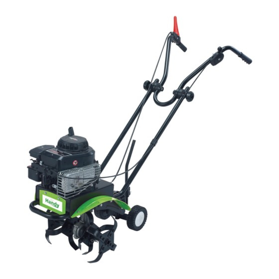
MAJOR PARTS Tine Clutch Control Throttle Control Lever Upper Handle Handle Adjustment Knob Lower Handle Depth Regulator Rod Transport Wheel Outer Tine Inner Tine Belt Guard Throttle Control - Controls the engine speed and stops the engine. Tine Clutch Control - Push down to engage the tines forward. Releasing returns the machine to neutral. - Page 5 MAJOR PARTS The tiller is supplied partly assembled. All parts included in the carton are shown below. Hardware Bag, including: Handle Adjustment Knobs (1 pair) Stop-Move Staff Bracket Wheel Support Bracket Chassis with Engine & Transmission Lower Handle - Left Lower Handle - Right Wheel (1 pair) Wheel Cover (1 pair)
-
Page 6: Assembly
ASSEMBLY A. Wheels: • Slide the tube sleeves into the wheels. • Mount the wheels on both sides of the bracket with • Attach the wheel covers. Lower Handles: • from the rear end of the tiller chassis. • Mounting holes for the adjustment knob are arranged in the top portion of each lower handle. - Page 7 ASSEMBLY cont’d D. Wheels Bracket: • Insert the wheels support rod into the holes on the tailpiece bracket. • Insert a Ø3 cotter pin through the hole in the support rod to secure it. Upper Handle: • Disassemble the handle adjustment knobs. •...
- Page 8 ASSEMBLY cont’d • Secure the throttle cable on the engine shield with a cable fastener. This will help prevent it from catching or snagging during normal operation. • Keep the other cable fastener as a spare. G. Depth Regulator Rod: •...
-
Page 9: Operation
OPERATION Starting the Engine: The tiller is supplied without fuel or oil. Fill the engine to the correct level with good quality SAE 30 engine oil. Fill the fuel tank with unleaded petrol, in accordance with the engine manual which is enclosed with the tiller. -
Page 10: Maintenance
MAINTENANCE Keeping your tiller in top running condition will prolong its life and help you obtain optimum performance whenever you wish to till your garden. Clean the tiller underneath the tine shield after each use. It is easier to clean off immediately after use before it has had time to dry. •... -
Page 11: Trouble Shooting
TROUBLE SHOOTING Problem Cause Remedy Engine fails to start Spark plug wire disconnected Attach spark plug wire securely to spark plug Out of fuel or stale fuel Fill with clean fresh petrol Throttle control lever not in the Move throttle lever to start correct starting position position Blocked fuel line... -
Page 12: Parts Diagram And List
PARTS DIAGRAM Page 12... -
Page 13: Parts List
PARTS LIST Part No Description Part No Description TH112-1 Engine TH112-2 Locknut M8 TH112-3 Washer 8 TH112-4 Hexangular Bolt M8x35 TH112-5 Basis TH112-6 Hexangular Bolt M8x40 U Shape Handle Front Plant TH112-7 TH118-8 TH112-9 Screw M6x12 TH112-10 Locknut M6 TH112-11 Transmission Case L TH112-12 Shaft... -
Page 14: Specification
SPECIFICATION Model THTILL3.5 Engine Briggs & Stratton Classic 35 Cultivating Width 380mm Cultivating Depth 250mm Tine Speed 120 rpm Sound Power Level 93 dB(A) Sound Pressure Level 81.1 dB(A) Vibrating Level on Handle Grips Left: 4.06 m/s² Right: 5.40 m/s²... - Page 16 To order spare parts and see the complete range of garden machinery and garden equipment from Handy, visit: www.thehandy.co.uk Spares & Support: 01793 333212...
Need help?
Do you have a question about the THTILL3.5 and is the answer not in the manual?
Questions and answers
How do I replace a broken drive belt??