Sign In
Upload
Download
Table of Contents
Contents
Add to my manuals
Delete from my manuals
Share
URL of this page:
HTML Link:
Bookmark this page
Add
Manual will be automatically added to "My Manuals"
Print this page
×
Bookmark added
×
Added to my manuals
Manuals
Brands
Ubiquiti Manuals
Antenna
airFiber X
Quick start manual
Ubiquiti airFiber X Quick Start Manual
2.4 ghz, 24 dbi slant 45 antenna for airfiber
Hide thumbs
Also See for airFiber X
:
User manual
(12 pages)
1
2
3
4
5
6
7
8
9
10
11
12
13
14
15
16
17
18
19
20
21
22
23
24
Table Of Contents
25
page
of
25
Go
/
25
Contents
Table of Contents
Bookmarks
Table of Contents
Package Contents
Installation Requirements
Hardware Overview
Hardware Installation
Mounting the GPS Antenna
Specifications
Safety Notices
Electrical Safety Information
Limited Warranty
Warranty Conditions
Limitation of Liability
Declaration of Conformity
Online Resources
Advertisement
Quick Links
Download this manual
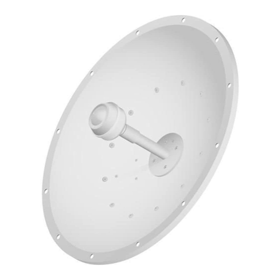
2.4 GHz, 24 dBi Slant 45
Antenna for airFiber
®
Model: AF-2G24-S45
Table of
Contents
Previous
Page
Next
Page
1
2
3
4
5
Advertisement
Table of Contents
Need help?
Do you have a question about the airFiber X and is the answer not in the manual?
Ask a question
Questions and answers
Related Manuals for Ubiquiti airFiber X
Radio Ubiquiti airFiber X User Manual
2.4 ghz, 3 ghz, 4 ghz, 5 ghz carrier backhaul radio (12 pages)
Antenna Ubiquiti airMAX Sector Quick Start Manual
2.4 ghz 2x2 mimo basestation sector antenna (21 pages)
Antenna Ubiquiti airMAX Titanium Sector AM-VSG-Ti Quick Start Manual
(20 pages)
Antenna Ubiquiti airGrid M5 HP AG-HP-5G23 Quick Start Manual
5 ghz high-performance integrated innerfeed antenna (25 pages)
Antenna Ubiquiti AG-HP-5G27 Quick Start Manual
5 ghz high-performance integrated innerfeed antenna (25 pages)
Antenna Ubiquiti air Grid M2 AGM2-HP-1114 Quick Start Manual
2.4 ghz high-performance integrated innerfeed antenna (21 pages)
Antenna Ubiquiti airMAX Omni AMO-5G10 Quick Start Manual
Dual polarity mimo omni antenna (17 pages)
Antenna Ubiquiti airMax Omni AMO-3G12 Quick Start Manual
3 ghz 2x2 mimo dual polarity omni antenna (17 pages)
Antenna Ubiquiti airMAX Omni Quick Start Manual
2.4 ghz 2x2 mimo dual polarity omni antenna (17 pages)
Antenna Ubiquiti airMAX Titanium Sector AM-V2G-Ti Quick Start Manual
Mid-gain advanced rf isolation variable beamwidth antenna (21 pages)
Antenna Ubiquiti airMAX Titanium Sector Quick Start Manual
5 ghz 2x2 mimo basestation antenna with variable beamwidth (21 pages)
Antenna Ubiquiti airMAX Sector AM-9M13 Quick Start Manual
900 mhz 2x2 mimo basestation sector antenna (21 pages)
Antenna Ubiquiti airMAX Sector Quick Start Manual
2.4 ghz 2x2 mimo basestation sector antenna (21 pages)
Antenna Ubiquiti airMAX RocketDish Quick Start Manual
Airmax carrier class 2x2 ptp bridge dish antenna (25 pages)
Antenna Ubiquiti airPrism AP-5AC-90-HD Quick Start Manual
(21 pages)
Antenna Ubiquiti airMAX airGrid M5HP Quick Start Manual
(29 pages)
This manual is also suitable for:
Af-2g24-s45
Table of Contents
Print
Rename the bookmark
Delete bookmark?
Delete from my manuals?
Login
Sign In
OR
Sign in with Facebook
Sign in with Google
Upload manual
Upload from disk
Upload from URL


Need help?
Do you have a question about the airFiber X and is the answer not in the manual?
Questions and answers