Table of Contents
Advertisement
Quick Links
Advertisement
Table of Contents

Related Manuals for Martin DMX Controller 2518


Summary of Contents for Martin DMX Controller 2518
- Page 1 2518 DMX Controller user manual...
- Page 2 © 1997 - 2000 Martin Professional A/S, Denmark. All rights reserved. No part of this manual may be reproduced, in any form or by any means, without permission in writing from Martin Professional A/S, Denmark. Printed in Denmark. P/N 35000001, rev. D...
-
Page 3: Table Of Contents
section 1 NTRODUCTION AFETY PRECAUTIONS ... 4 EATURES ... 4 CCESSORIES section 2 NSTALLATION ONNECTING THE SERIAL LINK ONNECTING THE POWER SUPPLY section 3 DDRESS AND MODE SETTING ... 8 DDRESS SETTING section 4 ROGRAMMING ... 10 ASIC CONTROL ROGRAMMING SCENES section 5 LAYBACK ONTROL PRECEDENCE... -
Page 4: Safety Precautions
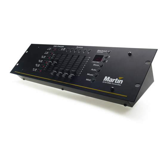
s e c t i o n 1 NTRODUCTION Thank you for selecting the Martin 2518 DMX Controller. This ruggedly built, easy to use controller offers 72-channel DMX control and multiple triggering options. Two 2518 DMX Controllers may be connected using the Tandem Connection Kit, P/N 91616005, to double the number of control channels and programmable scenes. -
Page 5: Installation
s e c t i o n 2 NSTALLATION The 2518 DMX Controller comes with the following: • IEC power cable • 5 meter 3-pin XLR-XLR cable • Termination plug • User manual DMX Output ONNECTING THE SERIAL LINK BOUT SERIALS LINKS The 2518 DMX Controller sends instructions through a serial data link. - Page 6 No adaptors are required to connect the 2518 DMX Controller to Martin fixture intro- duced since 1997 or any DMX-compatible fixture with 3-pin XLR connectors. The adaptors required to connect other fixtures are shown in Table 2. Standard Martin Polarity Pin 1 Pin 2 shield...
-
Page 7: Connecting The Power Supply
O BUILD THE SERIAL LINK Use shielded twisted-pair cable. A reliable data connection begins with the right cable. Microphone cable cannot transmit DMX data reliably over long runs. For best results, use only cable designed for RS-485 applications. Your Martin dealer has a range of cables, connectors, and adaptors designed for lighting control. -
Page 8: Address And Mode Setting
s e c t i o n 3 DDRESS AND MODE SETTING Each fixture connected to the serial link must have a unique address, also known as a start channel, which is the first channel the controller uses to send instructions to the fixture. - Page 9 when operated by a controller. Please refer to the user manuals for specific details on address and mode setting. DDRESSING EXAMPLE Table 5 shows how you could assign addresses for the following Martin equipment. • 4 MX-1s • 2 Punisher X250s •...
-
Page 10: Programming
s e c t i o n 4 ROGRAMMING Channel Master DMX Channels 1-36 (37-42) (37-72) 7-12 (43-48) 13-18 (49-54) 19-24 (55-60) 25-30 (61-66) 31-36 (67-72) Channel Button Lighting fixtures are controlled with the faders in groups of six channels. The DMX value is 0 when a fader is at the bottom and 255 when it is at the top. -
Page 11: Programming Scenes
Set effects with the faders. If there is no light, you may need to send a lamp-on command - see the fixture’s DMX protocol. Press the channel button again to turn fader control off. Repeat for other fixtures. To activate fader control of high channels, press the channel master to toggle to the high channels before pressing the channel button. - Page 12 Select scenes with the 6 scene buttons. DMX Channels (37-42) 7-12 (43-48) 13-18 (49-54) 19-24 (55-60) 25-30 (61-66) 31-36 (67-72) O CREATE AND SAVE A FLASH SCENE The flash scene can be executed at any time by pressing [Midi]. Program or select a scene to use as the flash scene. Press [Store].
-
Page 14: Playback
s e c t i o n 5 LAYBACK This section describes the built-in options for executing scenes: additional MIDI and tandem control options are covered in following sections. Press-and-hold to run current program on startup. DMX Channels (37-42) 7-12 (43-48) 13-18 (49-54) -
Page 15: Manual Execution
ANUAL EXECUTION To execute scenes manually, simply select a bank with the arrow buttons and select a scene with the scene buttons. The new bank does not begin to execute until a scene button has been pressed. To execute the flash scene, press [Midi]. UTO TRIGGER EXECUTION The auto trigger executes scenes at the rate that you set with the built-in timer. -
Page 16: Show Mode
HOW MODE In show mode, banks execute serially, allowing you to run some or all banks without additional input. There are 4 sets to choose from: banks 1-10, 11-20, 21-30, and 1-30. Banks execute 1-6 times before proceeding to the next bank. -
Page 17: Lackout Standby
O CLEAR AUTO START This procedure clears the memory lock and auto-start functions: to reset the memory lock see page 22. Turn off the controller. In tandem mode, turn off the top controller. Turn on the controller and immediately press and hold the top 3 channel buttons until “ON”... -
Page 18: Sing Midi
s e c t i o n 6 MIDI SING The 2518 DMX Controller provides additional playback options when connected to a MIDI device such as a keyboard, drum machine, or computer sound card. MIDI notes and program changes can be used to call specific scenes, change banks, and to trigger the next scene in the current bank. - Page 19 4. Generate the MIDI code: On you keyboard or other MIDI device, play the note or exe- cute the function to save with the scene. MIDI O CREATE A TRIGGER Press and hold [Midi], then press [Auto]. The display rolls. (Optional) Select a MIDI channel: Press the up and down arrow buttons to select a chan- nel between 1 and 16.
-
Page 20: Tandem Mode
s e c t i o n 7 ANDEM MODE DMX Channels 1 - 12 Autostart 13 - 24 25 - 36 37 - 48 49 - 60 61 - 72 DMX Channels 73 - 84 Autostart 85 - 96 97 - 108 109 - 120 121 - 132... - Page 21 Feature DMX output 72 channels Channel buttons Control 6 low + 6 high channels. Channel master Toggles between low and high channels, saves auto-start sequence. Scenes 6 per bank, 181 total. Display Shows bank with 2 digits, scene with 1 digit. Arrow buttons Select bank 1-30.
-
Page 22: Program Management
s e c t i o n 8 ROGRAM MANAGEMENT This section describes the features for saving and deleting the contents of the control- ler’s memory. There is also an Upload/Download Utility available from the Martin web site. This is a free Windows utility for managing lighting programs created with the 2518 DMX Controller. -
Page 23: Appendix A Troubleshooting
a p p e n d i x a ROUBLESHOOTING problem None of the fixtures respond to the controller. Some fixtures do not respond, respond erratically, or continuously reset. Save commands do not work. Fixtures do not execute pro- gramming on one or more channels. -
Page 24: Service
a p p e n d i x b ERVICE ALIBRATING FADERS If the controller does not output the full range of DMX values, or outputs different values from the same fader position, the faders can be recalibrated as follows. Press and hold [Blackout] to put the controller in standby mode. -
Page 25: Command Table
a p p e n d i x c OMMAND TABLE Function Save scene Save flash scene Execute flash scene Set auto-trigger Toggle music trigger Toggle show mode Set show mode banks Set show mode loops Blackout Standby Clear blackout or standby Save auto-start configuration Clear auto-start configuration Toggle tandem mode... -
Page 26: Appendix D Specifications
a p p e n d i x d PECIFICATIONS IMENSIONS • Height ... 95 mm (3.7") • Length ... 483 mm (19.0") • Width ... 130 mm (5.1") • Weight ... 2.8 kg (6.1 lb) • Rack size ...19” x 3U OWER CONSUMPTION •...
Need help?
Do you have a question about the DMX Controller 2518 and is the answer not in the manual?
Questions and answers