Table of Contents
Advertisement
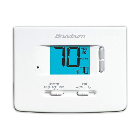
Non-Programmable
Thermostats
1020NC
1220NC
1 Specifications
2 About Your Thermostat
3 Installation
4 System Testing
Warning
Attention
Read all instructions before proceeding.
This thermostat requires 24 Volt AC Power or two (2) properly installed
"AA" Alkaline batteries for proper operation. When connecting 24 Volt
AC Power the batteries may be installed as a backup.
For use only as described in this manual. Any other use
will void warranty.
1 Specifications
This thermostat is compatible with:
• Single stage heat / cool conventional and heat pump systems
• Conventional systems up to 2 heat / 1 cool (1220NC only)
• Single compressor heat pump systems with an auxiliary heat stage (1220NC only)
• 250 – 750 millivolt heat only systems
Electrical and control specifications:
• Electrical Rating: 24 Volt AC
• 1 amp maximum load per terminal
• AC Power: 18 – 30 Volts AC
• DC Power: 3.0 Volt DC (2 "AA" Alkaline Batteries Included)
• Control Range: 45° – 90° F (7° – 32° C)
• Temperature Accuracy: +/- 1° F (+/- .5° C)
Terminations
• 1020NC – Rc, Rh, O, B, Y1, W1, G, C
• 1220NC – Rc, Rh, O, B, Y1, E/W1, G, W2, C
Single Stage Heat / Cool
Conventional and Heat Pump
Up to 2 Heat / 1 Cool
Conventional and Heat Pump
Model number is located on back of thermostat
5 Setting User Options
6 Operating Your Thermostat
7 Additional Operation Features
8 Thermostat Maintenance
Turn off power to the heating or cooling
equipment before installation.
For installation by experienced service
technicians only.
®
Detailed
Installer Guide
1020NCW-100-03
Advertisement
Table of Contents


Need help?
Do you have a question about the 1020NC and is the answer not in the manual?
Questions and answers
Temperature indicator is no longer lowering to the set point when cooling thus causing the air conditioner to run continuously.
The Braeburn 1020NC temperature indicator may not lower to the set point when cooling due to incorrect thermostat wiring, a malfunction in the cooling system, or the need to reset the thermostat. To troubleshoot, place the thermostat in OFF mode, remove the batteries (if equipped), press the reset button, replace the batteries, and switch to COOL mode. If the issue continues, there may be a problem with the cooling system that requires professional service.
This answer is automatically generated
Does the cooling supposed to flash are stay solid
The cooling indicator on the Braeburn 1020NC stays solid when the cooling system is running.
This answer is automatically generated
My thermostat temp. will not adjust. it won't go up and down
The Braeburn 1020NC thermostat may not adjust the temperature due to several reasons:
1. Low Battery – If the thermostat is powered by batteries and they are low, it may not function properly. Check for a low battery indication and replace the batteries if needed.
2. Temperature Limits – The thermostat has adjustable temperature limits. If the desired temperature is outside these limits, it will not adjust.
3. System Mode – Ensure the thermostat is set to the correct mode (HEAT or COOL) for the desired adjustment.
4. System Malfunction – If the heating or cooling system itself is not functioning, the thermostat will not be able to adjust the temperature.
5. Reset Required – Pressing the front reset button restores default settings, which may resolve any configuration issues.
If none of these resolve the issue, further troubleshooting may be required.
This answer is automatically generated
emergency setting will not come on What color wires turn on emergency setting