Advertisement
Table of Contents
- 1 About Your Thermostat
- 2 Installation
- 3 Connect Your Wires
- 4 Conventional Systems
- 5 Heat Pump Systems
- 6 Attach Thermostat to Sub-Base
- 7 System Testing
- 8 Setting User Options
- 9 Operating Your Thermostat
- 10 Additional Operation Features
- 11 Thermostat Maintenance
- 12 Limited Warranty
- Download this manual
Non-Programmable
Thermostats
Single Stage Heat / Cool
1020
Conventional and Heat Pump
Up to 2 Heat / 2 Cool Conventional
1220
Up to 2 Heat 1 / Cool Heat Pump
Model number is located on back of thermostat
1 Specifications
2 About Your Thermostat
3 Installation
4 System Testing
Warning
Turn off power to the heating or cooling
equipment before installation.
Attention
For installation by experienced service
technicians only.
Read all instructions before proceeding.
This thermostat requires 24 Volt AC Power or two (2) properly installed
"AA" Alkaline batteries for proper operation. When connecting 24 Volt
AC Power the batteries may be installed as a backup.
For use only as described in this manual. Any other use
will void warranty.
1 Specifications
This thermostat is compatible with:
Electrical and control specifications:
Terminations
®
Detailed
Installer Guide
5 Setting User Options
6 Operating Your Thermostat
7 Additional Operation Features
8 Thermostat Maintenance
1020W-100-03
Advertisement
Table of Contents

Related Manuals for Braeburn 1020


Summary of Contents for Braeburn 1020
- Page 1 Detailed Non-Programmable Installer Guide Thermostats Single Stage Heat / Cool 1020 Conventional and Heat Pump Up to 2 Heat / 2 Cool Conventional 1220 Up to 2 Heat 1 / Cool Heat Pump Model number is located on back of thermostat 1 Specifications...
-
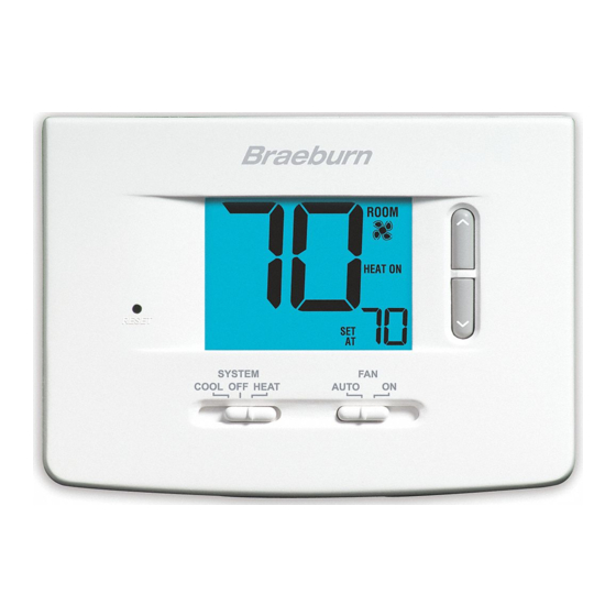
Page 2: About Your Thermostat
2 About Your Thermostat Room Temperature Reset Button Low Battery Indicator System Switch Quick Reference Instructions ...... Fan Indicator System Status Indicator Arrow Buttons Set Temperature Fan Switch Battery Compartment 3 Installation Warning Disconnect power before beginning installation. Thermostat Location... - Page 3 Install your new Braeburn thermostat in 5 basic steps: Install the Sub-Base: Drill 3/16” pilot holes in your desired location. Use supplied anchors for drywall or plaster. NOTE: After sub-base installation, you may insert the quick reference card into the slot on the top of the base.
-
Page 4: Connect Your Wires
Connect Your Wires Wiring Terminations Terminal Function Description Additional Terminations (1220 only) Terminal Function Description Conventional Systems Typical Wiring Configurations NOTE: The “Installer Switch” option will be configured in the next step. Heat Only or Millivolt Set Installer Switch to CONV W1/E [note 4] [note 1]... -
Page 5: Heat Pump Systems
Conventional Systems (cont.) 2 HEAT / 2 COOL Single or Dual Transformer (1220 Only) Set System Type to CONV [note 2] [note 2] [note 4] [note 1, 3] NOTES - Conventional Systems Provide disconnect and overload protection as required. Heat Pump Systems Typical Wiring Configurations NOTE: The “Installer Switch”... -
Page 6: Attach Thermostat To Sub-Base
Heat Pump Systems (cont.) NOTES - Heat Pump Systems W2 and E Provide disconnect and overload protection as required. Set Installer Switches Factory Setting Switch Default Options Comments NOTE: Installer switches are located on the back of the thermostat. The reset button must be pressed after making any changes to these switches. -
Page 7: System Testing
4 System Testing Warning Read Before Testing NOTE: The compressor delay can be bypassed by pressing the reset button on the front of the thermostat. All user settings will be returned to factory default. SYSTEM SYSTEM SYSTEM SYSTEM 5 Setting User Options Advanced User Options To enter the User Options menu, hold down both the buttons... -
Page 8: Operating Your Thermostat
Table of User Options User Factory Setting Options Default Options Comments 0.5, 1.0 or 2.0 1.0, 2.0, 3.0, 4.0 5.0 or 6.0 Detailed Explanation of User Options: Temperature Differential (User Option 1 and 2) 6 Operating Your Thermostat Setting the System Control Mode COOL HEAT Additional Switch Position (Model 1220 Only):... -
Page 9: Additional Operation Features
Temperature Adjustment Status Indicators HEAT ON COOL ON Additional Status Indicators (Model 1220 Only): EMER Resetting the Thermostat 7 Additional Operation Features Compressor Protection 8 Thermostat Maintenance Changing the Batteries If batteries are installed and they become low, a low battery indicator will appear in the display. -
Page 10: Limited Warranty
NOTE: We recommend replacing the thermostat batteries annually or if the thermostat will be unattended for an extended period of time. Thermostat Cleaning For troubleshooting tips, visit braeburnonline.com. Store this manual for future reference Limited Warranty YEAR LIMITED WARRANT Y ®...
Need help?
Do you have a question about the 1020 and is the answer not in the manual?
Questions and answers