Braeburn 1000NC User Manual
Non-programmable thermostats
Hide thumbs
Also See for 1000NC:
- User manual ,
- Detailed user manual (12 pages) ,
- Instructions manual (7 pages)
Table of Contents
Advertisement
Non-Programmable
Thermostats
1000NC
1200NC
1 Specifications
2 About Your Thermostat
3 Installation
4 System Testing
Warning
Attention
Read all instructions before proceeding.
This thermostat requires 24 Volt AC Power or two (2) properly installed
"AA" Alkaline batteries for proper operation. When connecting 24 Volt
AC Power the batteries may be installed as a backup.
For use only as described in this manual. Any other use
will void warranty.
1 Specifications
This thermostat is compatible with:
• Single stage heat / cool conventional and heat pump systems
• Conventional systems up to 2 heat / 1 cool (1200NC only)
• Single compressor heat pump systems with an auxiliary heat stage (1200NC only)
• 250 – 750 millivolt heat only systems
Electrical and control specifications:
• Electrical Rating: 24 Volt AC
• 1 amp maximum load per terminal
• AC Power: 18 – 30 Volts AC
• DC Power: 3.0 Volt DC (2 "AA" Alkaline Batteries Included)
• Control Range: 45° – 90° F (7° – 32° C)
• Temperature Accuracy: +/- 1° F (+/- .5° C)
Terminations
• 1000NC – Rc, Rh, O, B, Y, W, G, C
• 1200NC – R, O, B, Y1, E/W1, G, W2, C
Single Stage Heat / Cool
Conventional and Heat Pump
Up to 2 Heat / 1 Cool
Conventional and Heat Pump
Model number is located on back of thermostat
5 Setting User Options
6 Operating Your Thermostat
7 Additional Operation Features
8 Thermostat Maintenance
Turn off power to the heating or cooling
equipment before installation.
For installation by experienced service
technicians only. Follow applicable codes.
®
Detailed
User Guide
1000NCW-100-12
Advertisement
Table of Contents

Related Manuals for Braeburn 1000NC


Summary of Contents for Braeburn 1000NC
- Page 1 1 Specifications This thermostat is compatible with: • Single stage heat / cool conventional and heat pump systems • Conventional systems up to 2 heat / 1 cool (1200NC only) • Single compressor heat pump systems with an auxiliary heat stage (1200NC only) • 250 – 750 millivolt heat only systems Electrical and control specifications: • Electrical Rating: 24 Volt AC • 1 amp maximum load per terminal • AC Power: 18 – 30 Volts AC • DC Power: 3.0 Volt DC (2 “AA” Alkaline Batteries Included) • Control Range: 45° – 90° F (7° – 32° C) • Temperature Accuracy: +/- 1° F (+/- .5° C) Terminations • 1000NC – Rc, Rh, O, B, Y, W, G, C • 1200NC – R, O, B, Y1, E/W1, G, W2, C 1000NCW-100-12...
-
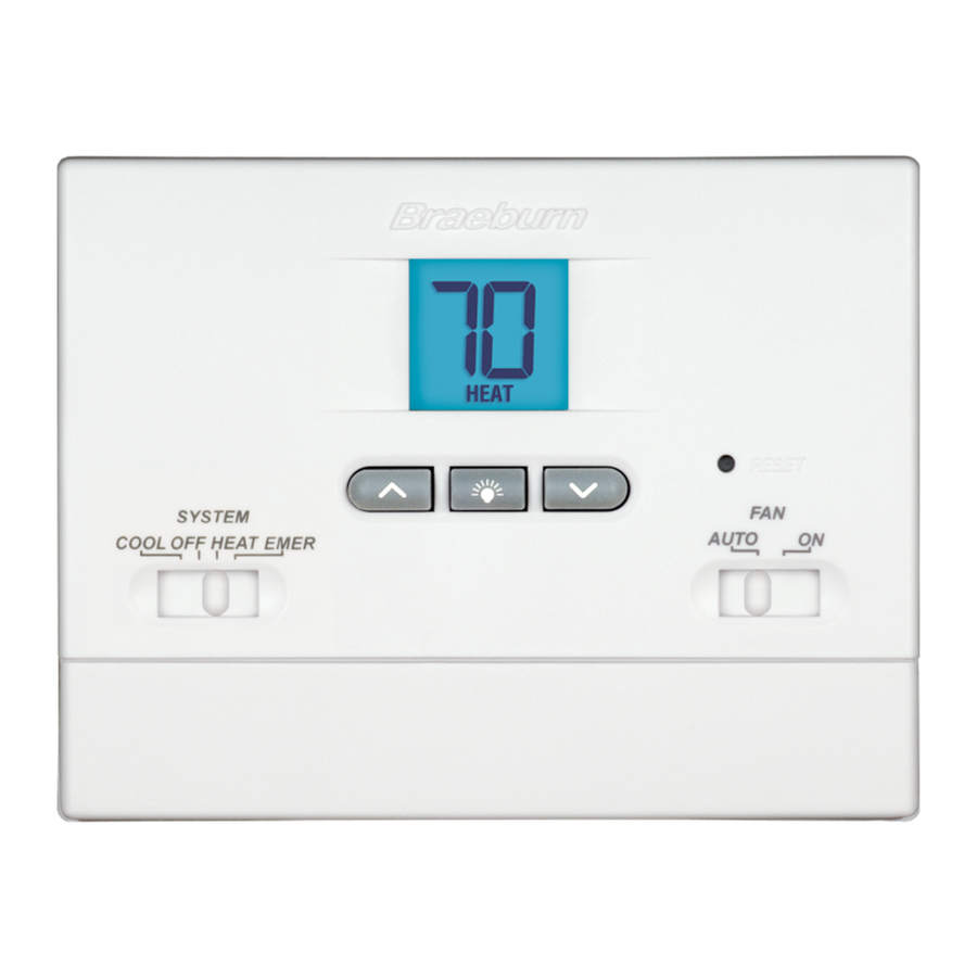
Page 2: About Your Thermostat
2 About Your Thermostat Room Temperature ... Displays the current room temperature Arrow Buttons ....Used to increase or decrease settings System Switch .... S elects Heat, Cool or Off Backlight Button .... I lluminates the display backlight Low Battery Indicator ..Indicates when the batteries need to be replaced System Status Indicator . .. D isplays information about the status of the system Reset Button ..... R esets thermostat back to factory defaults Fan Switch . - Page 3 Install your new Braeburn thermostat in 5 basic steps: 1 Install the Sub-Base 2 Provide Power 3 Connect Your Wires 4 Set Installer Switches 5 Attach Thermostat to Sub-Base Install the Sub-Base: • Remove the sub-base from the body of the thermostat. • Mount the sub-base as shown below: Drill 3/16” pilot holes in your desired location. Use supplied anchors for drywall or plaster. Provide Power...
- Page 4 Connect Your Wires Wiring Terminations Terminal Function Description Rc* Input 24 Volt AC Cooling Transformer (Dual Transformer Systems Only) Rh* Input Power Connection (24 Volt AC Heating Transformer or Millivolt Power Source) O Output Reversing Valve (Cool Active) B Output Reversing Valve (Heat Active) 1st Stage Compressor (appears as Y1 on 1200NC) Y Output G Output Fan Control W Output 1st Stage Conventional Heat C Input 24 Volt AC Transformer Common Additional Terminations (1200NC only) Terminal Function Description...
-
Page 5: Heat Pump Systems
Conventional Systems (cont.) 2 HEAT / 1 COOL Single Transformer (1200NC Only) Set System Type to NORM 24 Volt AC Power W1 Heat Relay Stage 1 W2 Heat Relay Stage 2 Y1 Compressor Relay Stage 1 Fan Relay 24 Volt AC Transformer Common [note 1] NOTES - Conventional Systems [1] If batteries are installed the 24 Volt AC common connection is optional [2] Remove factory installed jumper for dual transformer systems [3] In dual transformer systems, transformer common must come from cooling transformer [4] If needed for system Provide disconnect and overload protection as required. Heat Pump Systems Typical Wiring Configurations NOTE: The “Installer Switch”... - Page 6 Heat Pump Systems (cont.) NOTES - Heat Pump Systems [1] If batteries are installed the 24 Volt AC common connection is optional. [2] Select O for cool active or B for heat active. [3] Install a field supplied jumper between the W2 and E terminals if there is no separate emergency heat relay installed. Provide disconnect and overload protection as required. Set Installer Switches Factory Setting Switch Default Options Comments NORM Select for conventional systems NORM / HP NORM HP Select for heat pump systems Select for fahrenheit temperature scale F / C Select for celsius temperature scale HG Select for gas heat HE / HG...
-
Page 7: System Testing
4 System Testing Warning Read Before Testing • Do not short (or jumper) across terminals on the gas valve or at the heating or cooling system control board to test the thermostat installa- tion. This could damage the thermostat and void the warranty. • Do not select the COOL mode of operation if the outside temperature is below 50º F (10º C). This could possibly damage the controlled cool- ing system and may cause personal injury. • This thermostat includes an automatic compressor protection feature to avoid potential damage to the compressor from short cycling. When testing the system, make sure to take this delay into account. NOTE: The compressor delay can be bypassed by pressing the reset button on the front of the thermostat. All user settings will be returned to factory default. -
Page 8: Operating Your Thermostat
Table of User Options User Factory Setting Options Default Options Comments 0.5, 1.0 1 1st stage Select a 1st stage temperature or 2.0 differential differential of 0.5˚, 1.0˚ or 2.0˚F (0.2˚,0.5˚ or 1.0˚C) 1.0, 2.0, 2 2nd stage Select a 2nd stage temperature 3.0, 4.0, differential differential of 2˚, 3˚, 4˚, 5˚ or 6˚F 5.0 or 6.0 (1.0˚, 1.5˚, 2.0˚, 2.5˚ or 3.0˚C) (1200NC Only) Detailed Explanation of User Options: Temperature Differential (User Option 1 and 2) The differential setting is the temperature control range that your thermostat... -
Page 9: Additional Operation Features
Temperature Adjustment Press the or button to adjust the current set point temperature. Status Indicators Status indicators appear in the display to let you know if your system is heating, cooling or off. HEAT If flashing, indicates your heating system is running. COOL If flashing, indicates your cooling system is running. Additional Status Indicators (Model 1200NC Only): Indicates that the auxiliary stage of heating is running (Multi-Stage Systems only), or that the emergency heat system is running (heat pump systems only). Resetting the Thermostat This thermostat provides you with a reset button that will erase all of your user settings. To reset the thermostat, use a small object such as a tooth pick or paper- clip and gently press the button located inside the small hole on the front of the thermostat housing labeled “reset”. 7 Additional Operation Features Compressor Protection This thermostat includes an automatic compressor protection delay to avoid potential damage to your system from short cycling. This feature activates a short delay after turning off the system compressor. 8 Thermostat Maintenance Changing the Batteries Depending on your particular installation, this... -
Page 10: Limited Warranty
Thermostat Cleaning Never spray any liquid directly on the thermostat. Using a soft damp cloth wipe the outer body of the thermostat. Never use any abrasive cleansers to clean your thermostat. For troubleshooting tips, visit braeburnonline.com Store this manual for future reference. Limited Warranty When installed by a professional contractor, this product is backed by a 5 year limited warranty. Limitations apply. For limitations, terms and conditions, you may obtain a full copy of this warranty: · Visit us online: www.braeburnonline.com/warranty · Phone us: 866.268.5599 · Write us: Braeburn Systems LLC 2215 Cornell Avenue Montgomery, IL 60538 ® Braeburn Systems LLC 2215 Cornell Avenue • Montgomery, IL 60538 Technical Assistance: www.braeburnonline.com Call us toll-free: 866-268-5599 (U.S.) 630-844-1968 (Outside the U.S.) 1000NCW-100-12 ©2012 Braeburn Systems LLC • All Rights Reserved • Made in China.
Need help?
Do you have a question about the 1000NC and is the answer not in the manual?
Questions and answers
Comes on, but if I try to change temp setting, numbers distort and flash
The Braeburn 1000NC thermostat may flash in the display if EMER (emergency heat) is selected with the system switch. Additionally, flashing indicators such as HEAT or COOL show that the heating or cooling system is running. If the temperature adjustment causes the system to activate, the corresponding indicator may flash, which is normal and not a distortion. Display distortion may also occur if the temperature sensed is below 40˚F (4˚C), which is outside the display range, causing "LO" to appear. Allowing the thermostat to warm up can resolve this.
This answer is automatically generated