Advertisement
Quick Links
Download this manual
See also:
Owner's Manual
WEB ACCESS: http://www.yorkville.com
WORLD HEADQUARTERS
CANADA
Yorkville Sound
550 Granite Court
Pickering, Ontario
L1W-3Y8 CANADA
Voice: (905) 837-8481
Fax: (905) 837-8746
Quality and Innovation Since 1963
Printed in Canada
U.S.A.
Yorkville Sound Inc.
4625 Witmer Industrial Estate
Niagara Falls, New York
14305 USA
Voice: (716) 297-2920
Fax: (716) 297-3689
SERVICE MANUAL
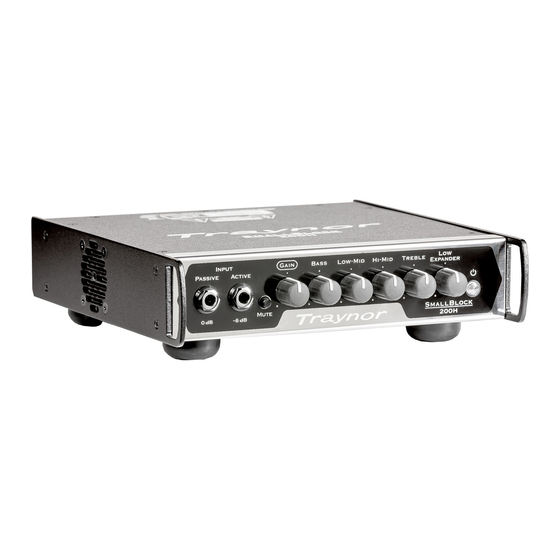
SB200H
TYPE: YS1109
SMT Disclaimer
Due to the complex nature of the use of SMT installed components
in Yorkville equipment, we highly caution all service technicians in
attempting to repair or replace SMT factory installed components.
Many of these components may be glued prior to initial soldering.
Replacing SMT components requires expensive
specialized de-soldering equipment and training.
Yorkville Sound will repair and replace defective SMT components
to ensure proper quality assurance and installation is maintained.
Manual-Service-SB200H-00-1v0 • August 6, 2015
Advertisement

Related Manuals for Traynor SB200H


Summary of Contents for Traynor SB200H
- Page 1 Replacing SMT components requires expensive specialized de-soldering equipment and training. Yorkville Sound will repair and replace defective SMT components Quality and Innovation Since 1963 to ensure proper quality assurance and installation is maintained. Printed in Canada Manual-Service-SB200H-00-1v0 • August 6, 2015...
- Page 2 IM PORTA N T S A F E T Y IN ST RUC TI ON S This lightning flash with arrowhead symbol, within The exclamation point within an equilatereal triangle is intended to alert the an equilateral triangle, is intended to alert the user to the presence of user to the presence of important operating and maintenance (servicing) uninsulated “dangerous voltage”...
- Page 3 Input Gain Bass Low-Mid Hi-Mid Treble Expander Passive Active Mute SmallBlock 200H Phone Jack Tuner Phones Post Lift SmallBlock SPEAKON™ 200H Pin Config 1+1– Power Spkr Out Line Out TRAYNOR SB200H Combi-Jack • Min 4 ohms...
- Page 4 Specifications Model: SB200H Type: bass amp Cabinet Impedance (ohms): 4 ohms Power @ min. impedance (watts): 200 watts Minimum Impedance (ohms): 4 ohms Burst Power - 2 cycle: 250 watts Input Channels: Channel 1 - inputs: passive 0 dB, active -6 dB...
- Page 5 Tone Control Bass 50 Hz Low Mid 400 Hz Hi Mid 1 kHz Treble 8 kHz Low Expander 40 Hz (boost) 550 Hz (cut) 10 kHz (cut)
- Page 6 DPDT PUSH SW PCMT BREAK B4 MAKE 8636 BUTTON 230X465 RND FLAT BLK (3425) 4455 _10K 5B R/A 12MM 4PIN HORZ 10029 SB200H KNB BLK WHT POINTER D SHAFT 4453 _50K B LIN 12MM 4PIN HORZ DT P40 4417 _10K 5B LIN 9MM HORIZONTAL P28...
- Page 7 Block Diagram for Small Block 200H DESIGNED AND MANUFACTURED BY YORKVILLE SOUND MODEL TYPE: YS1109 Speaker, Line & Headphone Outputs Buffer Balanced Tuner Out (front) Inputs TRS 1/4-inch Buffer 0 dB Unbalanced Input (for passive electronics) Balanced Line Out (rear) Pre-EQ GND Sw.
- Page 8 PATCH 02 18AWG 10.0 PH ONE END 9704 ICEPOWER 50ASX2(BTL) INT.AMP MODULE 3097 PATCH 03 22AWG 12.0 PH FLAT 10029 SB200H KNB BLK WHT POINTER D SHAFT 3098 PATCH 07 22AWG 12.0 PH FLAT 3100 PATCH 09 22AWG 05.0 XH FLAT 3425...
- Page 9 M1590-SB200H Parts Reference List 8/5/2015 YS # Description YS # Description YS # Description 5410 100P 100V 10%CAP T&R BEAD 4453 _50K B LIN 12MM 4PIN HORZ DT P40 4847 W250 2K2 5% T&R RES 5210 _22N 100V 10%CAP T&R RAD .2FLM...
- Page 10 +24VDC W7:I 9 NET00047 9 W5:I U1:C U2:C U5:C C200 U6:C U7:C U8:C C101 U14:C U15:C W3:B W3:C -24VDC -15V Product SB200H 1N4007 100N 100N 100N 100N 100N 100N 100N 100N C102 C265 TO220 6871 INPUTS PCB# M1590 Sheet 1N4732A...
- Page 11 220N U3:C U4:C 6K98 +15V M1590 100N 100N U3:E U4:E MODEL(S):- SMALL BLOCK - SB200H ICEpower50SAX2 block diagram DATE VER# DESCRIPTION OF CHANGE 17-Jun-2013 V01 First Release -15V 14-AUG-2013 PC8550: Routed auxiliary signal to headphones. - ML ICE50SAX2 10-APR-2014 V03 PC8635: See PC for changes.
-
Page 12: Block Diagram
YS#9704 DATASHEET Version 1.3 Page 4 of 32 ICEpower50ASX2 2x50W or 1x170W ICEpower Amplifier with integrated ICEpower Supply Block Diagram Figure 1: ICEpower50ASX2 block diagram Connection Diagram Figure 2: ICEpower50ASX2 connections... - Page 13 680P 20K0 330P 100N 100N 100N 100N 100N 100N 100N 2370 100N 100N C101 C102 2369 TO P102 M1590 V03 SB200H MC7915CT MC7815CT 2358 6871 6872 TO P103 6871 6872 2358 M1590 SB200H C265 100N 100N 100N 100N J109 TO P104...
- Page 14 SEE LAYOUT DIAGRAM M1590 PRODUCTION NOTES Remove this 1_ BREAK THE CONNECTION OF XLR J4 SEE PICTURE. piece. 2_ INSERT PUSHBUTTON KNOB ON SWITCH S1, S2 AND S3 BEFORE INSERTING INTO PCB. USE JIG AS SHOWN IN PICTURE Break this connection here.
- Page 15 SEE LAYOUT DIAGRAM M1590 MODEL(S):- SMALL BLOCK - SB200H DATE VER# DESCRIPTION OF CHANGE 17-Jun-2013 V01 First release 14-AUG-2013 PC8550: Routed auxiliary signal to headphones. - ML 10-APR-2014 PC8635: See PC for changes. GG 27-JAN-2015 PC#8734:Tack on 1N4007 YS#6438 diodes to U9,U11.
Need help?
Do you have a question about the SB200H and is the answer not in the manual?
Questions and answers