Advertisement
Advertisement
Table of Contents

Related Manuals for Aleko AR2000


Summary of Contents for Aleko AR2000
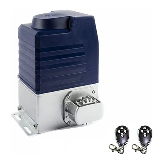
- Page 1 Sliding Gate Operator User’s Manual Model: AR2000...
-
Page 2: Table Of Contents
AR2000 SLIDING GATE OPERATOR OUTLINE ………………………3 1. Important safety information ……………………………………3 2. Main features ……………………………3 3. Technical parameters ……………4 4. Working principle and main structure ………………………5 5. Installation and adjustment …………………………………………8 6. Electrical …………………………………………10 7. Control ……………………………………15 8. Maintenance …………………………………16... -
Page 3: Important Safety Information
AR2000 SLIDING GATE OPERATOR 1.Important safety information Carefully read and follow all safety precaution and warnings before attempting to install and use this operator, incorrect installation can lead to severe injury. The gate operator should be installed by a qualified technician; otherwise, serious personal injury or property damage may occur. -
Page 4: Working Principle And Main Structure
AR2000 SLIDING GATE OPERATOR 4. Working principle and main structure The device is composed of a single-phase motor, worm and worm gear. The main shaft of the motor rotates the worm with the clutch engaged, the worm rotates the worm gear and output gear, which pushes rack attached to the sliding gate, thus moving the gate. -
Page 5: Installation And Adjustment
95ºC and switch on the motor automatically when the temperature is lower than 60±5ºC. 5. Installation and adjustment The AR2000 rack-driven gate operator operates by forcing a drive rack past a drive gear. The entire configuration is shown in the diagram below. Fig.4... - Page 6 AR2000 SLIDING GATE OPERATOR Conduit In order to protect the wires, conduit must be preset into the concrete when it is poured. Wires within the conduit shall be located or protected so that no damage can result from contact with any rough or sharp part.
- Page 7 AR2000 SLIDING GATE OPERATOR Fig.6 Magnets for limit switch Install the magnet as shown in Fig.7 and Fig.8 below. The magnet and limit switch are used to control the position of the gate. When the magnet is installed, release the gear clutch and push the sliding gate manually to pre-determine the position.
-
Page 8: Electrical
AR2000 SLIDING GATE OPERATOR It can be adjusted Lower bracket Magnet Rack Higher bracket Fig.8 6. Electrical Make sure that the power is OFF before making any electrical connections. Remove the cover of the control box, perform the wiring and replace the cover again. (Refer to Fig.9 control board scheme and wiring notes) Fig.9 Control board scheme... - Page 9 AR2000 SLIDING GATE OPERATOR Wiring notes for control board 1.Fuse: 10A, Ø5x20 2. Power Input: E (Earth), L (Live), N (Neutral) AC110V 3. Motor: U (com), V (Positive direction), W (Opposite direction), E (grounding) 4. Capacitor: 14uF 5. Alarm lamp: AC110V 6.
-
Page 10: Control
AR2000 SLIDING GATE OPERATOR Not used Open Signal Control board Button switch keypad terminal X7 Schematic diagram Wiring diagram 15. Output power supply: +12V (DC +12V), COM (CO),DET (Loop detector), I.R. (Infrared N.C) Terminal X8, No.15 Terminal X8, No.15 Terminal... - Page 11 AR2000 SLIDING GATE OPERATOR Button 1 Button 3 Button 2 Button 4 Fig.10 Remote control Adding extra remote controls (Learn): Press the button ‘AN’ (See Fig.9 terminal 17) on the control board, then the ‘LED2’ will be on and turn off, the beeper will ring about 1 second, then press the remote control button which you want to use, the ‘LED2’...
- Page 12 AR2000 SLIDING GATE OPERATOR Set auto-close function (This feature can be selected to make the gate stay open for some seconds before it automatically closes. The auto-close time can be adjusted to between 0 and 44 seconds.): please turn on the first and the second DIP-switch (See Fig.9 terminal 18) to ON position.
- Page 13 AR2000 SLIDING GATE OPERATOR Cancel width / auto-close function of pedestrian mode ﹡Cancel both width and auto-close function of pedestrian mode: Please turn on the first and the second DIP-switch (See Fig.9 terminal 18) to ON position. Press button 4 to open the gate (see Verify open direction section).
- Page 14 AR2000 SLIDING GATE OPERATOR Adjustment of the auto-reverse function: rotate the Force Adj. ‘VR’ knob (see Fig.9 terminal 7) with a screwdriver, the resistance may be increased or decreased by rotating clockwise or counterclockwise. Note: if the gate fails to reverse in the event of obstruction, then the opening force or closing force should be checked for conformity with requirements and adjusted accordingly.
-
Page 15: Maintenance
AR2000 SLIDING GATE OPERATOR 8. Maintenance: Please check and add transformer oil (DB25-GB2536) regularly, you may change the oil according the weather. If the temperature is lower than –20ºC, you can select #45 oil. Table 3 Parameters of DB25 transformer oil Kinematic viscosity (20ºC) -
Page 16: Troubleshooting
AR2000 SLIDING GATE OPERATOR 9. Troubleshooting Table 4 Trouble Possible causes Solutions The wire connector terminal block becomes Check wire connector terminal block. loose. Motor only runs in one direction. Check limit switch wire connector terminal The limit switch wire connector terminal block block.
Need help?
Do you have a question about the AR2000 and is the answer not in the manual?
Questions and answers