Table of Contents
Advertisement
Available languages
Available languages
8XT
8XT
8XT
8XT
coaxial enclosure
coaxial enclosure
coaxial enclosure
coaxial enclosure
8XT
8XT
8XT
8XT
enceinte coaxiale
enceinte
enceinte
enceinte
VERSION 1.3
VERSION 1.3
VERSION 1.3
VERSION 1.3
coaxiale
coaxiale
coaxiale
w w w . l - a c o u s t i c s . c o m
USER MANUAL
MANUEL D'UTILISATION
EN
FR
Advertisement
Chapters
Table of Contents

Related Manuals for L-Acoustics 8XT


Summary of Contents for L-Acoustics 8XT
- Page 1 coaxial enclosure coaxial enclosure coaxial enclosure coaxial enclosure enceinte coaxiale enceinte coaxiale enceinte enceinte coaxiale coaxiale VERSION 1.3 VERSION 1.3 VERSION 1.3 VERSION 1.3 USER MANUAL MANUEL D’UTILISATION w w w . l - a c o u s t i c s . c o m...
- Page 2 w w w . l - a c o u s t i c s . c o m...
-
Page 3: Safety Warnings
SAFETY WARNINGS SAFETY WARNINGS ® All information hereafter detailed applies for the L-ACOUSTICS 8XT Coaxial Enclosure, designated in this section as ‘‘the product’’. Symbol description Throughout this manual the potential risks are indicated by the following symbols: The WARNING symbol indicates a potential risk of physical harm to the user or people within close proximity to the product. - Page 4 8 8 8 8 XT C C C C OAXIAL ENCLOSURE OAXIAL ENCLOSURE OAXIAL ENCLOSURE OAXIAL ENCLOSURE user manual user manual user manual user manual VERSION 1.3 Water and moisture Even if the product is weather-resistant, it can not be exposed to moisture (rain, sea spray, shower, steam) for a long period of time, nor put in direct contact or partially immersed in water.
-
Page 5: Ec Declaration Of Conformity
13 rue Levacher Cintrat Parc de la Fontaine de Jouvence 91462 Marcoussis Cedex France States that the following product: Loudspeaker enclosure, 8XT Is in conformity with the provisions of: Machinery Directive 2006/42/EC Low Voltage Directive 2006/95/EC Applied rules and standards:... -
Page 6: Table Of Contents
Connecting the 8XT to the LA4......................14 7.3.3 [8XT_FR_100], [8XT_FI_100], and [8XT_MO_100] presets.............14 “HYBRID’’ mode .............................15 7.4.1 Description............................15 7.4.2 Connecting the 8XT and SB118 to the LA4..................15 7.4.3 [8XT_SB118] preset.........................16 CARE AND MAINTENANCE Maintenance information ..........................17 Testing procedure ............................17 8.2.1 Check of transducer and enclosure acoustic behavior................17 8.2.2... -
Page 7: Introduction
® Thank you for purchasing the L-ACOUSTICS 8XT Coaxial Enclosure. This manual contains essential information on installing and operating the product correctly and safely. It is necessary to read this manual carefully in order to become familiar with these procedures. -
Page 8: Xt Coaxial Range
SP.7, SP10, and SP25 loudspeaker cables with respective lengths of 0.7 m/2 ft, 10 m/30 ft, and 25 m/80 ft. These cables allow connection of the 8XT and 12XT enclosures to the LA4 amplified controller. Each cable is a 4-conductor cable with 4 mm conductor cross-section (13 SWG, 11 AWG) and features ®... - Page 9 12XT 115XT HIQ ETR8-2 ETR12-2 ETR15 XTLIFTBAR SB118 SOUNDVISION LA NETWORK MANAGER Figure 1: XT range components (part 1) w w w . l - a c o u s t i c s . c o m 8XT_UM_ML_1-3 7 7 7 7 en...
- Page 10 8 8 8 8 XT C C C C OAXIAL ENCLOSURE OAXIAL ENCLOSURE OAXIAL ENCLOSURE OAXIAL ENCLOSURE user manual user manual user manual user manual VERSION 1.3 LA-RAK with 3 LA8 SP.7 SP10 SP25 DO10 DO25 DO.7 DOFILL-LA8 Figure 2: XT range components (part 2) w w w .
-
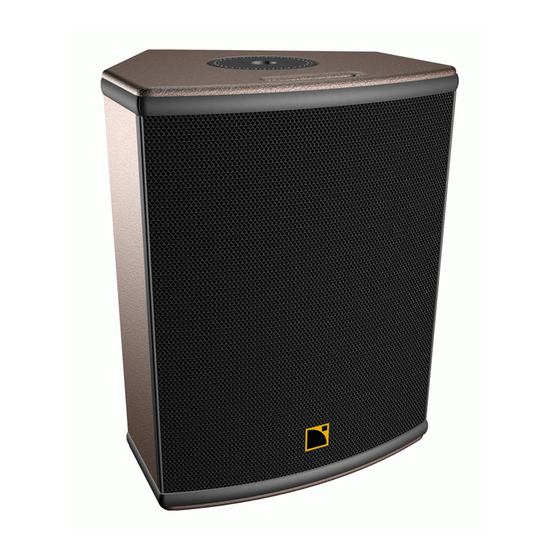
Page 11: 8Xt Coaxial Enclosure
The wedge-shaped cabinet design makes the 8XT perfectly suited to all stacked sound reinforcement applications. The cabinet can also be flown as well as pole, wall, or ceiling-mounted. The 8XT cabinet is made of high grade Baltic birch plywood with remarkable mechanical and acoustical properties for improved long term durability. -
Page 12: Installation
Stacking with two fixed angle settings of 30° and 40° with regard to the vertical. * A safety eyebolt accessory can be added using the M8 insert located on the rear face of the 8XT enclosure. Note: The “M6” and “M8” notations refer to the European standard (see applicable external documentation). - Page 13 Length for two 8XT (4 load) According to the calculation in Table 1, one SP25 cable (4 mm², 25 m) can be used to power two 8XT in parallel (4 load) with a damping factor still greater than 20. w w w . l - a c o u s t i c s . c o m...
-
Page 14: Operation
Connecting the 8XT to the LA4 Each 8XT enclosure must be connected to an LA4 output channel ranging from channel 1 through 4. An additional 8XT enclosure can be connected in parallel with each of the first ones. Therefore a single LA4 amplified controller can drive up to eight 8XT enclosures (see Figure 5). -
Page 15: 8Xt_Fr], [8Xt_Fi], And [8Xt_Mo] Presets
OUT 3 (IN B) OUT 2 (IN A) Note: This drawing is only a cabling scheme and does not represent a valid configuration. Figure 5: Eight 8XT enclosures connected to an LA4 controller 7.2.3 [8XT_FR], [8XT_FI], and [8XT_MO] presets The [8XT_FR] ‘‘FRONT’’ preset features LF and HF shelving EQ for standalone FOH applications without subwoofers. -
Page 16: High-Pass" Mode
Connecting the 8XT to the LA4 Each 8XT enclosure must be connected to an LA4 output channel ranging from channel 1 through 4. An additional 8XT enclosure can be connected in parallel with each of the first ones. Therefore a single LA4 amplified controller can drive up to eight 8XT enclosures (see Figure 6). -
Page 17: Hybrid'' Mode
Connecting the 8XT and SB118 to the LA4 The 8XT and SB118 enclosures connect to the LA4 outputs as follows: channels 1 and 3 are dedicated to one SB118 enclosure each, and channels 2 and 4 to 8XT enclosures. Each 8XT enclosure can be paired in parallel with an additional 8XT. -
Page 18: 8Xt_Sb118] Preset
OUT 3 (IN B) OUT 2 (IN A) Note: This drawing is only a cabling scheme and does not represent a valid configuration. Figure 7: Four 8XT and two SB118 enclosures connected to an LA4 controller 7.4.3 [8XT_SB118] preset The [8XT_SB118] preset features a HF shelving EQ for FOH applications. The crossover frequency between the LF and HF sections is set at 100 Hz. -
Page 19: Care And Maintenance
Oxidation-resistant screws and rigging points. However, in order to ensure product performance and safety, it is essential to frequently inspect the 8XT cabinet and its internal components. These checks need to be done on a regular basis depending on the conditions of system use. -
Page 20: Transducer Service
8 8 8 8 XT C C C C OAXIAL ENCLOSURE OAXIAL ENCLOSURE OAXIAL ENCLOSURE OAXIAL ENCLOSURE user manual user manual user manual user manual VERSION 1.3 Transducer service 8.3.1 LF loudspeaker If damaged, the 8” LF loudspeaker should be removed and repaired or replaced as described below. Recone kits are ®... -
Page 21: Spare Parts And Recommended Tools
HF driver or diaphragm replacing procedure 1. To install a full HF driver: Install the new driver on the heat dissipation plate (if necessary, add a few additional thermal paste above the old thermal paste on the driver in a continuous circular way). ®... -
Page 22: Specifications
8 8 8 8 XT C C C C OAXIAL ENCLOSURE OAXIAL ENCLOSURE OAXIAL ENCLOSURE OAXIAL ENCLOSURE user manual user manual user manual user manual VERSION 1.3 9 9 9 9 SPECIFICATIONS SPECIFICATIONS SPECIFICATIONS SPECIFICATIONS Reference Frequency response Usable bandwidth (-10 dB) 65 Hz - 20 kHz ([8XT_FR] preset) Maximum SPL... - Page 23 DÉCLARATIONS DE SÉCURITÉ DÉCLARATIONS DE SÉCURITÉ ® Les informations détaillées ci-dessous s’appliquent à l’Enceinte Coaxiale L-ACOUSTICS 8XT, dénommée par la suite ‘‘le produit’’. Symboles utilisés Tout au long de ce manuel les risques potentiels sont signalés par les symboles suivants : Le symbole WARNING signale un risque d’atteinte à...
- Page 24 ENCE ENCE ENCE ENCEINTE COAXIALE INTE COAXIALE INTE COAXIALE INTE COAXIALE m m m m anuel d’utilisation anuel d’utilisation anuel d’utilisation anuel d’utilisation VERSION 1.3 Eau et humidité Bien que peu sensible à l’humidité, le produit ne peut être exposé de manière durable à des projections d’eau (pluie, embruns, douches, vaporisation) ni être au contact de l’eau ou partiellement immergé, sous peine de détérioration irréversible de certains des composants exposés.
- Page 25 13 rue Levacher Cintrat Parc de la Fontaine de Jouvence 91462 Marcoussis Cedex France Déclare que le produit suivant : Enceinte acoustique, 8XT Est conforme aux dispositions de : Directive Machine 2006/42/CE Directive Basse Tension 2006/95/CE Règles et standards appliqués : EN ISO 12100-1 : 2004 (Sécurité...
- Page 26 7.3.3 Les presets [8XT_FR_100], [8XT_FI_100], et [8XT_MO_100]............14 Le mode “HYBRIDE” ............................15 7.4.1 Description............................15 7.4.2 Raccordement des enceintes 8XT et SB118 au LA4 ................15 7.4.3 Le preset [8XT_SB118] ........................16 ENTRETIEN ET MAINTENANCE Informations pour la maintenance ........................17 Procédure de vérification..........................17 8.2.1 Vérification des transducteurs et du comportement acoustique de l’enceinte ........17...
-
Page 27: Introduction
® Merci d’avoir fait l’acquisition de l’Enceinte Coaxiale L-ACOUSTICS 8XT. Ce manuel contient les informations indispensables au déroulement en toute sécurité des procédures d’installation et d’utilisation du produit. Il est nécessaire de lire attentivement ce manuel pour se familiariser avec les procédures. - Page 28 L-ACOUSTICS SP.7, SP10, et SP25 de longueurs respectives 0,7 m/2 ft, 10 m/30 ft, et 25 m/80 ft pour connecter les enceintes 8XT et 12XT au contrôleur amplifié LA4. Chaque câble ® comporte 4 conducteurs de section 4 mm (13 SWG, 11 AWG) et est muni de connecteurs Speakon 4 points.
- Page 29 12XT 115XT HIQ ETR8-2 ETR12-2 ETR15 XTLIFTBAR SB118 SOUNDVISION LA NETWORK MANAGER Figure 1 : Éléments de la gamme XT (partie 1) w w w . l - a c o u s t i c s . c o m 8XT_UM_ML_1-3 7 7 7 7 fr...
- Page 30 ENCE ENCE ENCE ENCEINTE COAXIALE INTE COAXIALE INTE COAXIALE INTE COAXIALE m m m m anuel d’utilisation anuel d’utilisation anuel d’utilisation anuel d’utilisation VERSION 1.3 LA-RAK avec 3 LA8 SP.7 SP10 SP25 DO10 DO25 DO.7 DOFILL-LA8 Figure 2 : Éléments de la gamme XT (partie 2) w w w .
- Page 31 L’ébénisterie à pans coupés est étudiée pour une utilisation polyvalente en posage. L’enceinte peut également être levée, montée sur pied, ou accrochée à un mur ou un plafond. L’enceinte 8XT est réalisée en multipli de bouleau balte de premier choix aux propriétés mécaniques et acoustiques remarquables pour une durabilité éprouvée.
-
Page 32: Installation
L’enceinte 8XT est pilotée et amplifiée par le contrôleur amplifié dédié L-ACOUSTICS LA4. Chaque canal d’amplification du LA4 peut alimenter une ou deux (en parallèle) enceintes 8XT. Pour plus de détail, merci de consulter le manuel d’utilisation ‘‘LA4’’ téléchargeable du site internet www.l-acoustics.com. - Page 33 Longueur pour une 8XT (8 ) Longueur pour deux 8XT (4 ) Selon le Tableau 1, un câble SP25 (4 mm², 25 m) peut alimenter 2 enceintes 8XT en parallèle (impédance 4 ) avec un facteur d’amortissement supérieur à 20.
-
Page 34: Exploitation
Le mode “LARGE BANDE” 7.2.1 Description Dans le mode “LARGE BANDE” les enceintes 8XT sont utilisées seules sur leur bande passante nominale (65 Hz – 20 kHz), pour des applications ne nécessitant pas de renfort sub-grave. 7.2.2 Raccordement de l’enceinte 8XT au LA4 Chaque enceinte 8XT est raccordée à... -
Page 35: Les Presets [8Xt_Fr], [8Xt_Fi], Et [8Xt_Mo]
OUT 2 (IN A) Note: Cette figure représente un schéma de câblage et non une configuration d’installation. Figure 5 : Huit enceintes 8XT connectées à un contrôleur LA4 7.2.3 Les presets [8XT_FR], [8XT_FI], et [8XT_MO] Le preset ‘‘FRONT’’ [8XT_FR] inclut des shelvings LF et HF adaptés aux applications de façade sans renfort sub-grave. -
Page 36: Le Mode "Passe-Haut
7.3.2 Raccordement de l’enceinte 8XT au LA4 Chaque enceinte 8XT est raccordée à une sortie du contrôleur amplifié LA4, successivement de 1 à 4 pour les quatre premières. Une enceinte 8XT supplémentaire peut être connectée en parallèle avec chaque première. Un seul contrôleur amplifié... -
Page 37: Le Mode "Hybride
Les enceintes 8XT et SB118 sont raccordées aux canaux d’amplification du LA4 de la manière suivante : les canaux 1 et 3 sont dédiés chacun à 1 enceinte SB118, les canaux 2 et 4 aux enceintes 8XT. Il est possible d’associer une seconde enceinte 8XT en parallèle avec chaque première. -
Page 38: Le Preset [8Xt_Sb118]
OUT 2 (IN A) Note : Cette figure représente un schéma de câblage et non une configuration d’installation. Figure 7 : Quatre 8XT et deux SB118 connectées à un contrôleur amplifié LA4 7.4.3 Le preset [8XT_SB118] Le preset [8XT_SB118] inclut un shelving HF adapté aux applications de façade. Le raccordement entre les sections LF et HF se situe à... -
Page 39: Informations Pour La Maintenance
Toutefois, pour assurer les performances et la sécurité du produit, il est indispensable de vérifier fréquemment l’état de l’enceinte 8XT et de ses organes internes. La fréquence de ces vérifications dépend des conditions d’utilisation du système. La procédure de vérification comprend essentiellement trois étapes décrites en section 8.2. Si un transducteur doit être réparé... -
Page 40: Maintenance Des Transducteurs
ENCE ENCE ENCE ENCEINTE COAXIALE INTE COAXIALE INTE COAXIALE INTE COAXIALE m m m m anuel d’utilisation anuel d’utilisation anuel d’utilisation anuel d’utilisation VERSION 1.3 Maintenance des transducteurs 8.3.1 Haut-parleur LF Si le haut-parleur LF 8’’ est détérioré il doit être démonté et réparé ou remplacé selon la procédure suivante. Des kits ®... -
Page 41: Pièces Détachées Et Outils Recommandés
Remplacement du moteur HF ou du diaphragme 1. Pour installer un moteur HF entier : Installer le nouveau moteur sur la plaque de dissipation thermique (si nécessaire, ajouter un peu de pâte thermique sur l’ancienne encore présente sur le moteur dans un mouvement circulaire continu). ®... - Page 42 ENCE ENCE ENCE ENCEINTE COAXIALE INTE COAXIALE INTE COAXIALE INTE COAXIALE m m m m anuel d’utilisation anuel d’utilisation anuel d’utilisation anuel d’utilisation VERSION 1.3 9 9 9 9 SPÉCIFICATIONS TECHNIQUE SPÉCIFICATIONS TECHNIQUE SPÉCIFICATIONS TECHNIQUES S S S SPÉCIFICATIONS TECHNIQUE Référence Réponse en fréquence Bande passante utile (-10 dB)
- Page 43 w w w . l - a c o u s t i c s . c o m...
- Page 44 Document reference: 8XT_UM_ML_1-3 _________________ ® © 2009 L-ACOUSTICS . All rights reserved. No part of this publication may be reproduced or transmitted in any form or by any means without the express written consent of the publisher. _________________ Distribution date: November 9 , 2009 w w w .
Need help?
Do you have a question about the 8XT and is the answer not in the manual?
Questions and answers