Table of Contents
Advertisement
EVERLAST
POWER i-MIG 200
CC/CV mig/stick WELDER
CC
CV
GMAW
SMAW
IGBT
DC
120/240V
DV
Operator's Manual for the Power i-MIG 200
Safety, Setup and General Use Guide
everlastwelders.com
GMAW/smaw
1-877-755-9353
329 Littlefield Ave. South San Francisco, CA 94080 USA
Rev. 2
0 1020101-15
Specifications and Accessories subject to change without notice.
Advertisement
Table of Contents

Related Manuals for Everlast POWER i-MIG 200


Summary of Contents for Everlast POWER i-MIG 200
- Page 1 POWER i-MIG 200 CC/CV mig/stick WELDER GMAW/smaw GMAW SMAW IGBT 120/240V Operator’s Manual for the Power i-MIG 200 Safety, Setup and General Use Guide Rev. 2 0 1020101-15 everlastwelders.com Specifications and Accessories subject to change without notice. 1-877-755-9353 329 Littlefield Ave. South San Francisco, CA 94080 USA...
-
Page 2: Table Of Contents
Table of contents Section……………………………………………….Page Letter to the Customer …………………..………… Everlast Contact Information…………….…………. Safety Precautions…………………………………… Introduction and Specifications…..………………… Overview of Parameters and Specifications……. Technical Parameters……………………………... General Description, Purpose and Features……. Set Up Guide and Component Identification….…... Suggested Settings…….…………………...…….. Connections and Polarity…………………………. -
Page 3: Letter To The Customer
It is also important so that we may track your satisfaction with Everlast products and services. If you are unable to register by web- site, contact Everlast directly through the sales department at the main customer service number in your country. -
Page 4: Everlast Contact Information
Serial number: _____________________________ Model number: _____________________________ Date of Purchase:___________________________ Contact Information Everlast US: Everlast consumer satisfaction email: sales@everlastwelders.com Everlast Website: everlastwelders.com Everlast Technical Support: support@everlastwelders.com Everlast Support Forum: http://www.everlastgenerators.com/forums/index.php Main toll free number: 1-877-755 WELD (9353) 9am—5pm PST M-F 11am-4pm PST Sat. -
Page 5: Safety Precautions
Safety Precautions Everlast is dedicated to providing you with the best possible equipment and service to meet the demanding jobs that you have. We want to go beyond delivering a satisfactory product to you. That is the reason we offer technical support to assist you with your needs should an occasion occur. - Page 6 SAFETY PRECAUTIONS These safety precautions are for protection of safety and health. Failure to follow these guidelines may result in serious injury or death. Be careful to read and follow all cautions and warnings. Protect yourself and others. Welding and cutting processes produce high levels of ultraviolet (UV) radiation that can cause se- vere skin burn and damage.
- Page 7 SAFETY PRECAUTIONS WARNING! Persons with pacemakers should not weld, cut or be in the welding area until they consult with their physician. Some pacemakers are sensitive to EMF radiation and could severely malfunction while welding or while being in the vicinity of someone welding. Serious injury or death may occur! Welding and plasma cutting processes generate electro-magnetic fields and radiation.
- Page 8 SAFETY PRECAUTIONS WARNING! Electrical shock can kill. Make sure all electrical equipment is properly grounded. Do not use frayed, cut or otherwise damaged cables and leads. Do not stand, lean or rest on ground clamp. Do not stand in water or damp areas while welding or cutting. Keep work surface dry. Do not use welder or plasma cutter in the rain or in extremely humid conditions.
-
Page 9: Introduction And Specifications
Section 1 Introduction and Specifications Overview of Parameters and Features* Power i-MIG 200** Amp Range (MIG) 110V/120V: 30-125 Amps 220V/240V: 30-200 Amps Volt Range (MIG) 110/120V: 15.5-20.3V 220V/240V: 15.5-26 Volts Duty Cycle at Max Rated Amps MIG: 35% @ 200 Amps Stick 35% @ 160 Amps... -
Page 10: Technical Parameters
Section 1 Introduction and Specifications EVERLAST MIG/STICK INVERTER SERIAL NO. MODEL: Power i-MIG 200 EN/ IEC60974.1 110V: 30-125A; 15.5-20.3V 220V: 30-200 A; 15.5-26 V 100% 200 A 160 A 130 A (220V) 20.5V (220V) 125A 100A (110V) 20.3V (110V) 110V: 10-100A; 20.4V-24V 220V: 10-160 A; 20.4-24 V... -
Page 11: General Description, Purpose And Features
MIG and Stick welding tasks anywhere wire is not the best solution. power is available. The Power i-MIG 200 can be used with .023”-.045” wire and features an 8” diameter spool 1.3 Installation. The basic construction of the Power i capacity. -
Page 12: Setup Guide And Component Identification
Section 2 Setup Guide and component Identification GENERAL POLARITY RECOMMENDATIONS* Table 1 *Consult manufacturer directions of filler material. There are exceptions! PROCESS TORCH POLARITY WORK POLARITY MIG (GMAW) FLUX CORE (FCAW) STICK (SMAW) GAS SELECTION GUIDE Table 2 PROCESS MIG (GMAW) STEEL 80/20 Ar/CO2 or 75/25 Ar/CO2 for short Circuit MIG MIG (GMAW) STAINLESS 98/2 Ar/O2 or TriMix... -
Page 13: Connections And Polarity
Be sure to use the special serrated drive rollers for Flux Core, which are available as an option. Contact Everlast to purchase additional drive rolls. See next page for instructions on chang- ing polarity and drive rollers. -
Page 14: Installing Mig Wire
Reversal of the lower roller may be necessary. To reverse the roller, remove the black thumb screw securing the drive roll. Pull the drive roll off, and flip the drive .6mm=.023”-.025” .8mm= .030”-.035” roll over. Reassemble and tighten roller. If larger roller is needed, contact Everlast. .9mm-.035” 1.2mm=.045”... -
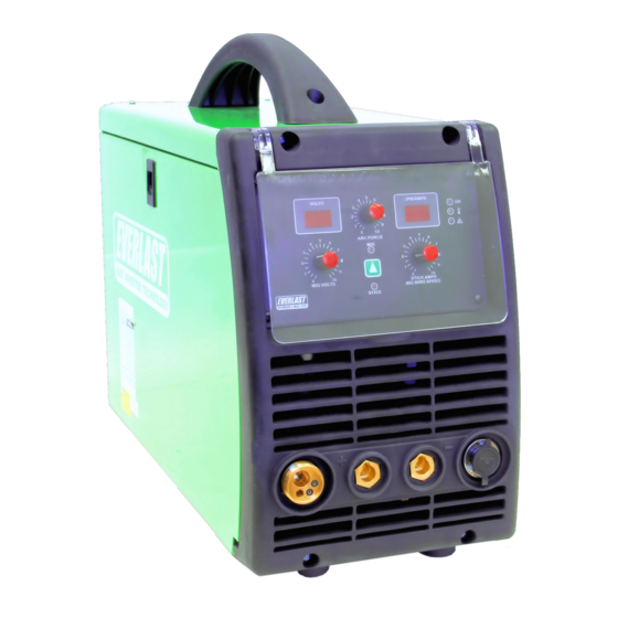
Page 15: Front View Main Panel
MIG: Wire Speed (in/min) Stick: Amps 7. Control (Spool Gun) 8. Negative Connector MIG: Work Clamp Stick: Work Clamp 9. Positive Connector 10. MIG Torch Euro Connector Flux Core: Work Clamp Stick: Torch FRONT VIEW/ MAIN PANEL POWER i-MIG 200... -
Page 16: Front Panel Item Description And Explanation
A person can either adjust the arc force to overcurrent. If the overcurrent does not clear have a familiar feel, or to improve arc behavior when the unit is turned back on, contact Everlast whenever welding position or condition change. technical support. - Page 17 Section 2 Setup Guide and component Identification speed or amps may result in what appears to be a jump by several amps or inches per minute. This is normal and not something that is critical to fine tuning the machine to where it is needed. Often a light touch will result in the correct setting or with- in an amp or two.
-
Page 18: Side View
Section 2 Setup Guide and component Identification 3. Burn Back Control Timer 2. Polarity Buss Bar 1. Wire Spool Holder Assy. Burn Back 4. Wire Feeder Assy. SIDE VIEW POWER i-MIG 200... -
Page 19: Side View Item Description And Explanation
2. Polarity Buss Bar. Note the “+” and “-” sym- Everlast, including flux core. Each groove will bols located on the inside of the unit next to drive at least two sizes of wire. For example if the buss bar terminals. -
Page 20: Rear View Back Panel
Setup Guide and component Identification 2. Main Power Switch 1. Gas Connector (Barb Type) 4. 5 A fuse for Wire Feeder FUSE INLET 3. Power Cord/NEMA 6-50 Plug 1x110/220V 5. Fan Shroud 6. Ground (Where required) REAR VIEW/BACK PANEL POWER i-MIG 200... -
Page 21: Rear Panel Item Description And Explanation
10% variation. Consult your generator manufacturer for information regarding the clean power rating on specific units. Everlast does not pro- vide a list of approved generators. Manufactur- ers rate their units as clean power independent- ly according to industry standards. - Page 22 Section 2 Setup Guide and component Identification BASIC MIG OPERATION General Setup of Amps and Volts. them either too hot or too cold. For some people, it When welding with the Power i-MIG, the two main may not even close. However, nothing can substi- functions that require adjustment are Voltage and tute for watching the arc and listening to the sound Wire feed speed.
-
Page 23: Basic Mig Operation
Section 2 Setup Guide and component Identification BASIC MIG OPERATION While Everlast uses the term “arc force”, it is known wire. While ultimately there are limits to what by many different terms. Often it is referred to as any given wire can weld on the lower end of it’s inductance, choke or slope. - Page 24 Section 2 Setup Guide and component Identification BASIC MIG OPERATION released. porous weld. If the burn back control is set too long it can cause The end of the wire should be positioned just barely the wire to burn back into the tip itself and welding above the metal when the trigger is pulled for the of the wire to the tip.
- Page 25 Section 2 Setup Guide and component Identification BASIC MIG OPERATION novice welders. Stringers are simply straight beads sufficient level of deoxidizers such as silicone and that move forward with little or no side to side travel copper that are formulated to allow it to handle mi- or oscillation.
- Page 26 Section 2 Setup Guide and component Identification BASIC MIG OPERATION Besides a butt joint and lap joint which are often used DOUBLE V-GROOVE V-GROOVE (60-80°) for thinner metal gauges, consider using one of these groove joints for best welding results. When grinding or cutting the bevels, especially with a single V- groove, it may be beneficial to leave a small land with U-GROOVE...
- Page 27 Section 2 Setup Guide and component Identification BASIC MIG OPERATION Problem: Gun is not being held vertical from side to side. Wire is not being directed to the center of the puddle. This concentrates heat on one side of the joint and results in poor fusion on the neglected side.
- Page 28 Section 2 Setup Guide and component Identification BASIC MIG OPERATION Characteristics: Concave weld, poor filling, possi- ble undercutting resulting in weak weld. Possible Causes: Voltage too high, not enough wire speed, too short of wire stick out, wrong gun angle. Remedy: Decrease voltage, use push motion, in- crease wire speed.
-
Page 29: Stick Operation
Section 2 Setup Guide and component Identification STICK OPERATION STARTING METHODS Tapping Method Scratch/Match Method 1. Make sure the unit is turned on and the startup cycle has finished. 2. Select the Stick icon on the Process Selector. 3. Make sure electrode holder is in in the Positive connector and the work clamp is in the nega- tive connector. -
Page 30: General Notes Concerning Operation
There are also wire spool adapters available online from a variety of sources which allow the spool carrier to remain in place without disassembly. Everlast does not currently offer these direct for this machine. -
Page 31: Expanded View Of Mig Torch
Coaxial cable assy /16mmq/3m option. Everlast does not recommend installing torch cables longer than Cable thimble 12-16-25 MMQ 18 ft on the Power i-MIG 200 as feeding issues may occur. Euro-rear connector handle Retaining Screw M4*6 UNI 6107 Knurled locking nut... -
Page 32: Trouble Shooting
Wire continues feeding but no large diameter wires. Check power plug for problems. If easily tripped the Resistor value too low. (Contact Everlast if OC is tripping regularly with normal settings.) Potentiometer damaged. Repair or Replace it. Welding Voltage/Current is uncon- trollable Control board damaged.
Need help?
Do you have a question about the POWER i-MIG 200 and is the answer not in the manual?
Questions and answers