
Related Manuals for Vaillant VRT 340f


Summary of Contents for Vaillant VRT 340f
- Page 1 For the owner and heating engineer Operating and Installation Manual VRT 340f Room temperature thermostat VRT 340f...
-
Page 2: Table Of Contents
Recycling and disposal ..21 Description of the appliance . . . 8 Operation ....8 Operating and installation manual VRT 340f... - Page 3 Installation ....25 9.1 Place of installation ....... 25 14 Vaillant Service ... . . 39 9.2 Fitting the receiver ......26 9.3 Mounting the room temperature...
-
Page 4: Notes On The Documentation
Storage of the documents Caution! Please pass on this operating and Potentially dangerous situation installation manual to the owner of the for the product and environment. system in order for him/her to store it so Operating and installation manual VRT 340f... -
Page 5: Safety
• Symbol for a necessary task heating engineer, who is responsible for adhering to the existing standards and regulations. We accept no liability for any damage caused by failure to observe these instructions. Operating and installation manual VRT 340f... -
Page 6: Operating Manual
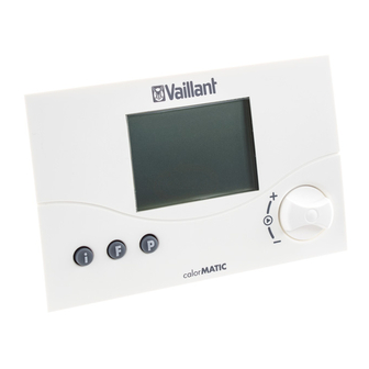
1 Overview of the device Operating manual Overview of the equipment Display 2 Dial (turn and click) Info button F Special functions button P Programming key/installer level Abb. 1.1 Overview of equipment Operating manual VRT 340f... -
Page 7: Overview Of The Display
2 Info level 3 Timer programming 4 Time/temperature display 5 Days of the week 6 Actual temperature 7 Operating modes 8 Special functions 9 Heating circuit symbol 10 Hot water symbol Fig. 2.1 Overview of the display Operating manual VRT 340f... -
Page 8: Description Of The Appliance
The VRT 340f enables you to specify the day of the week, the time and the room temperature using heating heating circuit symbol, if heating is programs. -
Page 9: Setting The Operating Modes
– the symbol for the selected mode flashes in the display. • Turn the dial until the desired operating mode appears on the display. The display switches back to normal mode after five seconds. Operating manual VRT 340f... - Page 10 Energy Saving: The heating circuit is operated according to the energy saving temperature "ECO“, regardless of the programme set on the room temperature thermostat. Operating manual VRT 340f...
- Page 11 Off:The heating circuit is off, provided that the set timer programme. The hot water the frost protection function (if the room symbol is not displayed. temperature is below 5°C) is not activated. Table 4.1 Operating modes Operating manual VRT 340f...
-
Page 12: Setting The Current Day And Time
WE = Wednesday you set the time. This allows automatic TH = Thursday switching from winter to summer time. FR = Friday SA = Saturday SU = Sunday • Press the dial. The hours start flashing. Operating manual VRT 340f... -
Page 13: Setting The Heating Times
23:30 6. Set the end time. — — — — — — You can define three time windows for 7:30 22:00 each day. — — — — — — Table 4.2 Default basic programme - heating Operating manual VRT 340f... - Page 14 TH = Thursday be changed (H1), which also FR = Friday flashes. SA = Saturday Select the desired time SU = Sunday window by turning the dial. Settings: H1, H2, H3 Operating manual VRT 340f...
-
Page 15: Setting The Room Temperature
You can set the room temperature directly from the basic display. You can also set or change the set-back Table 4.3 Setting time windows temperature "ECO“ in the basic display. Operating manual VRT 340f... -
Page 16: Activating Special Functions
The display switches back to normal Activating special functions mode after five seconds. You can access the special functions using the F button. You can activate the following functions: Operating manual VRT 340f... - Page 17 10 button. This function can only be seconds and the function is activated in automatic mode activated. To deactivate the function, all you need to do is press the F button. Operating manual VRT 340f...
-
Page 18: Info Level
- The name of the room temperature Turn the dial until the required thermostat (VRT 340f ) number of day's holiday - The quick veto room temperature appears. After 10 seconds the... -
Page 19: Changing The Battery
The battery chamber is located on the back of the regulator. The regulator must be taken off the wall Fig. 4.1 Releasing the locking hook plinth to change the battery. Operating manual VRT 340f... -
Page 20: Manufacturer's Warranty And Liability
(2x AAA-LR03; Fig. 4.2). Make sure that the polarity of the batteries is correct. Vaillant warranty We only grant a Vaillant manufacturers warranty if a suitably qualified engineer has installed the system in accordance with Vaillant instructions. The system owner will be granted a warranty in accordance with the Vaillant terms and conditions. -
Page 21: Recycling And Disposal
Recycling and disposal 6 Recycling and disposal Packaging Please leave the disposal of the Both your Valliant room temperature transport packaging to the qualified thermostat VRT 340f and its packaging servicing company which installed the consist mainly of recyclable raw appliance. materials. Appliance... -
Page 22: Installation Instructions
7 Information on installation and operation Installation instructions CE label The CE label shows that the VRT 340f room temperature thermostat, when Notes on the installation connected to Vaillant boilers, meets the and operation basic requirements of the Council of... -
Page 23: Intended Use
Information on installation and operation 7 Intended use The connection between the room The VRT 340f room temperature temperature thermostat and the heating thermostat is a state-of-the-art appliance unit is by radio. which has been constructed in Any other use or extended use is accordance with recognised safety considered to be improper. -
Page 24: Safety Instructions And Regulations
Only remove the room temperature thermostat from the wall mounting or from the plinth when it is potential free. Installation instructions VRT 340f... -
Page 25: Regulations
Choose a location where the room temperature thermostat is not affected by draughts from doors or windows, Installation instructions VRT 340f... -
Page 26: Fitting The Receiver
(2) into the chute which is revealed so that the pins on the back of the upper section fit into the receptacles. Fig. 9.1 Heating unit and fitting the receiver in the switchgear box Installation instructions VRT 340f... -
Page 27: Mounting The Room Temperature Thermostat
(1) off the wall plinth (3). • Drill two holes (2) of 6 mm diameter (as shown in fig. 9.2) and put in the supplied wall plugs. • Attach the wall plinth to the wall with the two screws provided. Installation instructions VRT 340f... -
Page 28: 10 Electrical Installation
Risk of fatal electric shock from touching live connections. Before carrying out work on the controller, switch off the power supply and secure it against being switched on again. Fig. 9.2 Mounting the room temperature thermostat Installation instructions VRT 340f... -
Page 29: Connecting The Receiver
The service/diagnostics level is also terminals 3 and 4 on the boiler. intended for the engineer and is designed to help during servicing. The receiver is fitted with three status LEDs which provides the following information to the system: Installation instructions VRT 340f... - Page 30 - Setting point for heating mode: 50 °C (the manual mode automatically switches to normal mode if a correct radio connection is made with the sender. yellow flashing Radio connection is made with the sender Table 11.1 Status display of the receiver Installation instructions VRT 340f...
-
Page 31: Installer Level
Press the P button to access the installer level. • Press the P button for approx. 10 seconds. The spanner symbol and the first parameter appear in the display. • Press the dial. You can select all the system parameters in turn. Installation instructions VRT 340f... - Page 32 0). You can set it to analogue mode by changing the parameter to 1. Correction of current room temperature Adjustment of the displayed value by up to max. +/- 3 °C Factory setting: 0 °C Installation instructions VRT 340f...
- Page 33 For activation of the (positive values: slow calendar reaction speed of the room temperature thermostat; negative values: faster reaction speed of the room Year setting temperature thermostat) For activation of the calendar Table 11.2 System parameters Installation instructions VRT 340f...
-
Page 34: Service/Diagnostics Level
First, a heating request for 50 °C is triggered to test communication with the boiler. Then you can select all the test options by pressing or rotating the dial. When you press the P button the display returns to basic mode. Installation instructions VRT 340f... - Page 35 (only up to the maximum supply button for 3 temperature of the boiler). seconds. Press Radio route Display RF On Press Display test All display elements are displayed. Press Software version The software version is displayed. Table 11.3 Service/diagnostic level Installation instructions VRT 340f...
-
Page 36: Handing Over The Appliance To The Owner
• Hand over the manuals intended for the owner as well as the documents of the appliance. • Go through the operating manual with him and answer his questions. Installation instructions VRT 340f... -
Page 37: 12 Troubleshooting
Fault signal Meaning Troubleshooting RF Err No radio connection to the radio Check the site of installation receiver on the heating unit BATT low battery condition, replacement Replace the batteries. required Table 12.1 Fault signals Installation instructions VRT 340f... -
Page 38: 13 Technical Data
Transmission capacity ≤ 1 (readiness) ≤ 15 (readiness) Current consumption Minimum cross-section of the connection lines 0,75 Level of protection IP 20 IP 20 Protection rating for regulator Dimensions Height/width/depth 97/146/27 85/148/30 Table 13.1 Technical data Installation instructions VRT 340f... -
Page 39: 14 Vaillant Service
Vaillant Service 14 14 Vaillant Service Vaillant Service To ensure regular servicing, it is strongly recommended that arrangements are made for a Maintenance Agreement. Please contact Vaillant Service Solutions (0870 6060 777) for further details. Installation instructions VRT 340f... - Page 40 Vaillant Ltd Vaillant House Medway City Estate Trident Close Rochester Kent ME2 4EZ Telephone 01634 292300 Fax 01634 290166 www.vaillant.co.uk info@vaillant.co.uk...
Need help?
Do you have a question about the VRT 340f and is the answer not in the manual?
Questions and answers