
Related Manuals for Vaillant VR 51


Summary of Contents for Vaillant VR 51
- Page 1 Operating and installation instructions Room thermostat VR 51 GB, IE Publisher/manufacturer Vaillant GmbH Berghauser Str. 40 D-42859 Remscheid Tel. +49 21 91 18-0 Fax +49 21 91 18-2810 info@vaillant.de www.vaillant.de...
-
Page 2: Table Of Contents
Contents Contents Safety ................4 Action-related warnings ..........4 1.2 Intended use ..............5 1.3 General safety information .........6 Notes on the documentation ........9 2.1 Observing other applicable documents ....9 2.2 Storing documents ............9 2.3 Validity of the instructions .........9 System and product description ......10 3.1 Component of the ambiSENSE system ....10 3.2 Design of the product ..........11 3.3 Display ................12... - Page 3 Contents 6.3 Using the Boost function ..........31 6.4 Activating/deactivating the operation lock ..32 Troubleshooting ............32 Detecting and rectifying faults ........32 7.2 Command not confirmed ...........33 7.3 Resetting to factory setting ........34 Care and maintenance ..........37 8.1 Caring for the product ..........37 8.2 Changing batteries ............38 Decommissioning ............42 9.1 Decommissioning the product .........42...
-
Page 4: Safety
Safety Safety Action-related warnings Classification of action-related warnings The action-related warnings are classified in accordance with the severity of the pos- sible danger using the following warning signs and signal words: Warning symbols and signal words Danger! Imminent danger to life or risk of severe personal injury Danger! Risk of death from electric... -
Page 5: Intended Use
Safety Caution. Risk of material or environmental damage Intended use In the event of inappropriate or improper use, damage to the product and other property may arise. You can use the room thermostat for the time-controlled regulation of individual rooms. Intended use includes the following: –... -
Page 6: General Safety Information
Safety Intended use also covers installation in accordance with the IP class. Any other use that is not specified in these instructions, or use beyond that specified in this document shall be considered improper use. Any direct commercial or industrial use is also deemed to be improper. - Page 7 Safety > Only carry out the activities for which instructions are provided in these oper- ating instructions. 1.3.2 Risk of material damage caused by frost > Do not install the product in rooms prone to frost. 1.3.3 Danger caused by a malfunction >...
- Page 8 Safety 1.3.4 Risk of material damage caused by unsuitable environmental conditions The electronics may be damaged if you install the product in an unsuitable envi- ronment. > Only install the product in dry, dust-free rooms. > Ensure that the product is not exposed to constant solar or heat irradiation, vibrations or mechanical loads.
-
Page 9: Notes On The Documentation
Storing documents > Keep this manual and all other applica- ble documents safe for future use. Validity of the instructions These instructions apply only to: Product article number VR 51 0020247923 Operating and installation instructions 0020248975_01... -
Page 10: System And Product Description
System and product description System and product description Component of the ambiSENSE system The product is part of the ambiSENSE room climate solution and communicates via a radio protocol. All products in the ambiSENSE room climate solution can be configured via the VRC 700 app using a smartphone. -
Page 11: Design Of The Product
System and product description thermostats in cycles, meaning that the room temperature can be regulated even more precisely. The installation takes place by screwing in or sticking the mounting plate and fasten- ing in the clip-on frame that is supplied. The product can be integrated into existing switch series. -
Page 12: Display
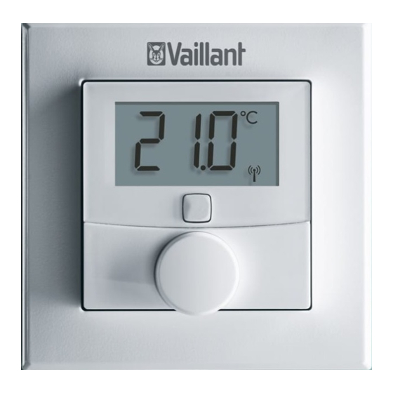
System and product description Mounting plate 2 Clip-on frame 3 Setting wheel 4 System button 5 Display 6 Room thermostat Display Note The background lighting for the display is switched off in standby mode. To activate the background lighting, press the setting wheel once. - Page 13 System and product description MANU BOOST Operation lock active 2 Unit for the numeric display 3 Automatic decrease active 4 Radio data transmission 5 Low battery charge 6 Boost mode active 7 Manual mode active 8 Target/actual temperature 9 Setting mode active Operating and installation instructions 0020248975_01...
-
Page 14: Radio Operation
System and product description Radio operation The radio signal is transmitted on a non-exclusive transmission path. Faults can therefore not be ruled out. Interfer- ences may, for example, be caused by switching operations, electric motors or defective electrical units. The range inside buildings may differ con- siderably from the range outdoors. -
Page 15: Flashing Sequence Of The Signal Led
System and product description Flashing sequence of the signal LED Flashing Required Meaning sequence activity Brief period Radio trans- Wait until the of flashing mission/ transmission orange transmission has ended. attempt or configuration data is trans- ferred 1 x long Process con- Continue with period of... - Page 16 System and product description Flashing Required Meaning sequence activity Brief period Pairing mode Enter the dig- of flashing active its of the unit orange (every number to 10 seconds) confirm. Brief period Batteries flat Replace the of lighting up batteries. orange (after a green or red reception...
-
Page 17: Duty Cycle Limit
System and product description Flashing Required Meaning sequence activity Long and Update to the New software brief period unit software is trans- of flashing (OTAU = Over ferred. (Dura- orange (alter- the Air tion: Up to 12 nating) Update) hours) This does not affect how the product... - Page 18 System and product description onds in 1 hour). The product complies with this directive. normally reached. In individual cases, e.g. during start-up or the new installation of a system, increased and radio-intensive pair- ing processes may mean that this limit is not reached.
-
Page 19: Ce Marking
Direc- tive 2014/53/EU. The complete text for the EU Declaration of Conformity is available at: http://www.vaillant-group.com/doc/ doc-radio-equipment-directive/. Checking the scope of delivery > Check that the scope of delivery is com- plete and intact. -
Page 20: Integration Into The Ambisense System
Integration into the ambiSENSE system Number Designation Clip-on frame Mounting plate 1.5 V LR03/Micro/AAA batteries 5 mm rawl plug, 3 x 30 mm cross-head screws Double-sided adhesive strips Unit number sticker Operating and installation instructions Integration into the ambiSENSE system Pairing To ensure that the room thermostat is integrated into the ambiSENSE system... - Page 21 Integration into the ambiSENSE system to the VR 920 Internet gateway. You should therefore first set up the VR 920 Internet gateway via the VRC 700 app in order to be able to use ambiSENSE units in the system. Then pair the product via the VRC 700 app as follows.
- Page 22 Integration into the ambiSENSE system the digits of the unit number (SGTIN = Serialised Global Trade Item Number) in the app to confirm or use the smart- phone to scan the QR code. Note You can find the unit number and the QR code on the enclosed sticker and in the product’s battery com- partment.
-
Page 23: Set-Up
Set-up Set-up Defining the installation site Install the room thermostat: – On an interior wall of the living room Height: 1.5 m above the floor In a frost-free room Do not install the room thermostat: – Close to heat sources, such as radiators, chimney walls, television sets, direct sunlight –... - Page 24 Set-up Installing the room thermostat You can either install the room thermostat in the clip-on frame that is also supplied or you can integrate it into an existing switch series. To install it in the clip-on frame, you can use either the supplied double-sided adhesive strips or the supplied screws to secure the room thermostat to the wall.
- Page 25 Set-up > Secure the adhesive strips (1) to the rear of the mounting plate (2) in the markings provided for that purpose. Ensure that you can read the writing on Operating and installation instructions 0020248975_01...
- Page 26 Set-up the rear and that the clips for the mounting plate can click into the open- ings on the room thermostat. > Remove the plastic film from the adhe- sive strips. > Press the assembled room thermostat onto the wall with the rear at the required position.
- Page 27 Set-up Screw mounting > Select a suitable installation site in the room. Operating and installation instructions 0020248975_01...
- Page 28 Set-up Note Ensure that no cables or pipes are routed within the wall. > Use the mounting plate to mark two of the drill holes located diagonally oppo- site to each other. Note Ensure that the arrow on the front of the mounting plate is pointing upwards.
- Page 29 Set-up click into the openings on the rear of the room thermostat. Installation in multiple combinations You can also use the room thermostat with clip-on frames from other manufacturers or you can integrate it into a multiframe. The room thermostat fits into frames from the following manufacturers: –...
-
Page 30: Operation
Operation porting rings that have already been attached and is aligned to these. Operation Changing the operating mode Automatic mode: The heating programme that is set via the VRC 700 app is active. Manual mode: You can set the temperature on the product or by using the VRC 700 app. -
Page 31: Using The Boost Function
Operation You can also use the VRC 700 app in automatic mode to manually set a desired temperature (Quick Veto) that overwrites the current time programme for a certain amount of time. The duration for which the manually set temperature should apply can be individually defined here. -
Page 32: Activating/Deactivating The Operation Lock
Troubleshooting – The Boost function is automatically terminated after 300 seconds. Activating/deactivating the operation lock You can use the relevant room settings in the VRC 700 app to activate and deacti- vate the product‘s operation lock. Troubleshooting Detecting and rectifying faults Conditions: The room temperature does not reach the set temperature >... -
Page 33: Command Not Confirmed
Troubleshooting > Check whether room air can circulate freely around the room thermostat, and that the room thermostat is not covered by furniture, curtains or other objects. Conditions: The display is off > Press the setting wheel briefly once. > Check whether the “Low battery” sym- bol is shown in the display. -
Page 34: Resetting To Factory Setting
Troubleshooting – Transceiver cannot implement the com- mand (load failure, mechanical block- age, etc.) – Defective transceiver Resetting to factory setting Note All settings will be lost. 1. Remove the batteries. (Page 38) Operating and installation instructions 0020248975_01... - Page 35 Troubleshooting 2. Re-insert the batteries in accordance with the polarity markings and, at the same time, press and hold the system Operating and installation instructions 0020248975_01...
- Page 36 Troubleshooting button for four seconds until the signal LED starts to rapidly flash in orange. 3. Release the system button. 4. Press the system button again for four seconds until the signal LED lights up green. 5. Release the system button to complete the process of restoring the factory set- tings.
-
Page 37: Care And Maintenance
Care and maintenance Care and maintenance Caring for the product Caution. Risk of material damage caused by unsuitable cleaning agents. > Do not use sprays, scouring agents, detergents, solvents or cleaning agents that con- tain chlorine. > Clean the casing with a damp cloth and a little solvent-free soap. -
Page 38: Changing Batteries
Care and maintenance Changing batteries 1. Remove the product from the mounting plate. 2. Always change all the batteries (1) at the same time. – Battery type: LR03/Micro/AAA 3. Do not use rechargeable batteries. 4. Insert the batteries, making sure that the poles are the right way round. - Page 39 Care and maintenance Note After inserting the batteries, the product first runs through a selftest for approx. two seconds. Initialisa- tion then takes place. 5. After inserting the batteries, observe the flashing sequence of the signal LED. – Self-test successful: Signal LED lights up orange first and then green.
- Page 40 Care and maintenance > Ensure that you use the correct battery type when replacing batteries. > Dispose of used batteries in accordance with the instruc- tions in this manual. 8.2.2 Leaking batteries Danger! Risk of chemical burns caused by leaking batteries! If the product is not used for several weeks, the batteries may leak.
- Page 41 Care and maintenance > Remove the batteries if you will be away for an extended period. > Take suitable measures to protect against chemical burns (e.g. wear protective gloves). 8.2.3 Batteries > Note the battery type, as described in these instructions; see section “Data plate”.
-
Page 42: Decommissioning
Decommissioning > Do not combine new and used batteries. > Insert the batteries, making sure that the poles are the right way round. > Remove the dead batteries from the product and dispose of them correctly. > Remove the batteries if you intend to store the product and not use it for an extended period and/or to scrap it. -
Page 43: Recycling And Disposal
Customer service Recycling and disposal If the product is labelled with this mark: > In this case, do not dispose of the prod- uct with the household waste. > Instead, hand in the product to a collec- tion centre for old electrical or elec- tronic appliances. -
Page 44: 11 Technical Data
11 Technical data 11 Technical data Parameter Value Battery type 2x 1,5 V LR03 / Micro / AAA 50 mA Current consumption Battery life 2 years IP rating IP 20 Degree of contamina- tion Maximum permitted 0 … 35 °C environmental temperature Height... - Page 45 Technical data Parameter Value Maximum transmission < 25 mW power Receiver category SRD category 2 Range outdoors 250 m (820 ft - 3 in) Duty cycle < 1% per h / < 10% per h Mode of operation Type 1 Operating and installation instructions 0020248975_01...
- Page 48 0020248975_01 Supplier Vaillant Ltd. Nottingham Road Belper Derbyshire DE56 1JT Telephone 0330 100 3461 info@vaillant.co.uk www.vaillant.co.uk © These instructions, or parts thereof, are protected by copyright and may be reproduced or distributed only with the manufacturer's written consent. We reserve the right to make technical changes.
Need help?
Do you have a question about the VR 51 and is the answer not in the manual?
Questions and answers