Vaillant VRC 470 Installation Instructions Manual
Hide thumbs
Also See for VRC 470:
- Installation insrtuctions (72 pages) ,
- Operating instructions manual (40 pages) ,
- Instruction manual (32 pages)

Related Manuals for Vaillant VRC 470


Summary of Contents for Vaillant VRC 470
-
Page 1: Installation Instructions
Installation instructions For the heating engineer Installation instructions VRC 470f GB, IE... -
Page 2: Table Of Contents
Reading the status of the cylinder charge pump ..............33 Functional description ...........28 8.5.4 Reading the status of the circulation pump ..33 Service information ..........28 8.5.5 Defining the day for executing the anti- 8.1.1 Entering contact details ..........28 Legionella function ...........33 Installation instructions VRC 470 0020116690_00... - Page 3 Defining the offset for charging the domestic hot water cylinder ........33 Technical data ............44 8.5.8 Defining the run-on time for the cylinder 13.1 Controller VRC 470 ..........44 charge pump ..............33 13.2 Sensor resistances ..........44 8.5.9 Activating parallel charging (domestic hot water cylinder and mixing circuit) ......34...
-
Page 4: Notes On The Installation Instructions
"Information/Serial number". It is in tural parts and components of the system when the second line of the display (¬ Operating instruc- installing the VRC 470 controller. tions). These installation instructions are enclosed with the var- ious system components as well as additional compo- CE label nents. -
Page 5: Safety
Nevertheless, there is a risk of death or serious injury to the operator or others or of damage > When installing the VRC 470, take account of the to the units and other property in the event of improper basic safety instructions and the warning notes that use or use for which they are not intended. -
Page 6: Requirements For Cables
> If thermostatic control is activated, advise the opera- tor that, in the room where the controller is mounted, all the radiator valves must be fully open. Installation instructions VRC 470 0020116690_00... -
Page 7: System Description
You can mount the controller on a wall using the wall of the heating as a function of the outside temperature. mounting base or in the controller slot of a Vaillant If the outside temperature is low, the controller boiler, without the wall mounting base. -
Page 8: Unit Design
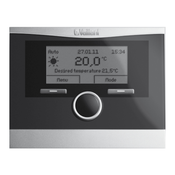
The solar module VR 68/2 can be used by the controller to control a solar system. Control Center VR 65 The Control Center VR 65 allows for the use of Vaillant low voltage "eBUS" controllers with valves and domestic hot water cylinders from the traditional 230 V range in the English market. - Page 9 VR 81/2. You can use the remote control unit VR 81/2 to set the parameter " Room temp. target". In addition, the controller displays service and fault mes- sages by means of symbols. Data interchange is via eBus line. Installation instructions VRC 470 0020116690_00...
-
Page 10: Installation
The installation location of the external sensor should – not fully protected from wind – not particularly draughty – not in direct sunlight – not affected by heat sources – on a north or north-west facing wall Installation instructions VRC 470 0020116690_00... -
Page 11: Mounting The Controller In The Living Room
> Drill two holes with 6 mm diameter in accordance with the mounting holes (3). > Insert the wall plugs supplied. > Insert the eBUS cable through one of the cable open- ing (4). Installation instructions VRC 470 0020116690_00... -
Page 12: Installing The External Sensor
– the VRC 9535 requires a 3-core connection cable Fig. 4.3 Fitting the external sensor VRC 693 Mounting holes 2 Cap nut for cable entry point 3 Connection cable with drip loop 4 Wall mounting base 5 Housing cover Installation instructions VRC 470 0020116690_00... - Page 13 (Cable diameter: 4.5 mm to 10 mm). > Place the gasket between the wall mounting base and the housing cover. > Push the housing cover onto the wall mounting base until it clicks in position. Installation instructions VRC 470 0020116690_00...
-
Page 14: Electrical Installation
Connecting external sensor VRC 693 > Connect the 6-way edge connector (2) to slot X41 of Connection cable to the external sensor VRC 693 the PCB of the control cabinet. 2 6-way edge connector for plug location X41 (boiler) Installation instructions VRC 470 0020116690_00... -
Page 15: Connecting The Controller Installed In The Living Room
Connect the controller to the boiler as follows: > Connect the eBUS line to the terminals (1) of the pin header in the wall mounting base of the controller. > Connect the eBUS line to the terminal strip of the boiler (2). Installation instructions VRC 470 0020116690_00... -
Page 16: Start-Up
1) Appears only if solar module VR 68/2 is connected. 2) Appears only if solar station VMS is connected. 3) Appears only if mixing module VR 61/2 is connected. 4) Appears only if cylinder actoSTOR VIH RL is connected. Installation instructions VRC 470 0020116690_00... -
Page 17: Making Settings For The Operator
> Set the period for hot water production. > If relevant, set the period for circulation. Setting other parameters of the heating system You can set other parameters via the "Installer" operat- ing level, (¬ Section 7) and (¬ Section 8). Installation instructions VRC 470 0020116690_00... -
Page 18: Operation
"Menu" and list entry "Installer level". Several consecutive displays indicate possible additional heating circuits. Menu entries shown in grey are only available if a corre- sponding expansion module is connected. Installation instructions VRC 470 0020116690_00... -
Page 19: Menu Structure Overview
Room temp. target 20,0°C Room temp. currant 20,0°C Back Domestic hot water Back Load pump 5 min Paral. cyl. charge LP/ZP relay connection no connect. Back Change Fig. 7.1 Installer level menu structure Part 1 Installation instructions VRC 470 0020116690_00... - Page 20 Temperature 0,0°C ------------------------------------------------- Back Select Back Change Back Change Installer level Change code Change code Screed drying function New code Change code ------------------------------------------------- Back Select Back Change Fig. 7.2 Installer level menu structure Part 2 Installation instructions VRC 470 0020116690_00...
-
Page 21: Installer Level Overview
6) Appears only if no mixing module VR 61/2 is connected. * If there is no fault, then the status is "OK". If there is a fault, "Fault" appears here and you can read the error message (¬ Section 10.2) here. Installation instructions VRC 470 0020116690_00... - Page 22 6) Appears only if no mixing module VR 61/2 is connected. * If there is no fault, then the status is "OK". If there is a fault, "Fault" appears here and you can read the error message (¬ Section 10.2) here. Installation instructions VRC 470 0020116690_00...
- Page 23 6) Appears only if no mixing module VR 61/2 is connected. * If there is no fault, then the status is "OK". If there is a fault, "Fault" appears here and you can read the error message (¬ Section 10.2) here. Installation instructions VRC 470 0020116690_00...
- Page 24 6) Appears only if no mixing module VR 61/2 is connected. * If there is no fault, then the status is "OK". If there is a fault, "Fault" appears here and you can read the error message (¬ Section 10.2) here. Installation instructions VRC 470 0020116690_00...
- Page 25 6) Appears only if no mixing module VR 61/2 is connected. * If there is no fault, then the status is "OK". If there is a fault, "Fault" appears here and you can read the error message (¬ Section 10.2) here. Installation instructions VRC 470 0020116690_00...
- Page 26 6) Appears only if no mixing module VR 61/2 is connected. * If there is no fault, then the status is "OK". If there is a fault, "Fault" appears here and you can read the error message (¬ Section 10.2) here. Installation instructions VRC 470 0020116690_00...
- Page 27 6) Appears only if no mixing module VR 61/2 is connected. * If there is no fault, then the status is "OK". If there is a fault, "Fault" appears here and you can read the error message (¬ Section 10.2) here. Installation instructions VRC 470 0020116690_00...
-
Page 28: Functional Description
"Service" is displayed in the basic display of the controller. If a service appointment is saved in the boiler, the mes- sage "Service heat generator" appears on the boiler when this date is reached. Installation instructions VRC 470 0020116690_00... -
Page 29: Setting The Frost Protection Delay
(OT): OT –20 °C : preset duration of the pre-heat time OT +20 °C : no pre-heat time The duration of the pre-heat time is interpolated linearly between these two values. Installation instructions VRC 470 0020116690_00... -
Page 30: Setting The Raising Temperature
"Auto" mode and how much of the period is still remaining. To do this, the controller must be in "Automatic mode". The information is specified in hr:min. Installation instructions VRC 470 0020116690_00... -
Page 31: Setting The Room Temperature
[HEATING 1/2 ----] ¬ Summer mode offset This function allows you to define if the controller should automatically activate "Summer mode" based on a temperature calculation for all heating circuits. The controller remains in automatic mode. Installation instructions VRC 470 0020116690_00... -
Page 32: Setting The Heating Curve
– Night temperature: The heating function is switched on and the target room temperature is set to the set "Night temperature" and adjusted to the "Night tem- perature". Installation instructions VRC 470 0020116690_00... -
Page 33: System Configuration: Domestic Hot Water
70 °C (with 5 K hysteresis). The circulation pump is acti- circuit in particular, are enabled again. vated. Installation instructions VRC 470 0020116690_00... -
Page 34: Activating Parallel Charging
8.6.6 Reading the status of the multi relay Menu ¬ Installer level ¬ System configuration [Solar ----] ¬ Status multi relay Only with a connected VR 68/2 This function allows you to read the current status of the multi relay (On, Off). Installation instructions VRC 470 0020116690_00... -
Page 35: Reading The Runtime Of The Solar Pump
Menu ¬ Installer level ¬ System configuration 1 = Cylinder 1 is the cylinder with cylinder sensor SP1 [Solar ----] ¬ Solar circuit prot. 2 = Cylinder 2 is the cylinder with cylinder sensor TD1 Only with a connected VR 68/2 Installation instructions VRC 470 0020116690_00... -
Page 36: Defining The Maximum Temperature For Solar Cylinder
The difference value can be defined separately for two This function is only effective if "Diff.Reg." is selected connected solar cylinders. when setting the multi relay (¬ Section 8.6.12). Does not apply in combination with a VMS solar station. Installation instructions VRC 470 0020116690_00... -
Page 37: Selecting The Expansion Module For Sensor/ Actuator Test
This function allows you to change the access code for "Installer level" operating level. If the code is no longer available, you must reset the controller to the factory setting in order to obtain access to Installer level again. Installation instructions VRC 470 0020116690_00... -
Page 38: Operator Level Functions
– Set up time programmes for HEATING 1/HEATING 2, hot water production and the circulation pump – Plan days away from home (holiday function) – Plan days at home (bank holiday function) – Reset the solar gain Installation instructions VRC 470 0020116690_00... -
Page 39: Handing Over The Unit To The Owner
– the operator must ensure that the heating system remains in operation and rooms are heated ade- quately during periods of absence during frost, – the operator must observe the frost protection instructions. Installation instructions VRC 470 0020116690_00... -
Page 40: Fault Recognition And Clearance
Mixer module VR 61/2 Cable defective, plug connection not correct communication fault fault Sensor VF2 fault Fault in flow sensor VF2 Mixer module VR 61/2 Cable defective, plug connection not correct, flow sensor defective Tab. 10.1 Error messages Installation instructions VRC 470 0020116690_00... -
Page 41: List Of Errors
Fault in flow sensor VF2 Mixer module VR 61/2 Cable defective, plug connection not correct, flow sensor defective Tab. 10.2 List of error messages 10.3 Restore factory settings You can reset the settings to the factory settings (¬ operating instructions). Installation instructions VRC 470 0020116690_00... -
Page 42: Warranty And Customer Service
Vaillant instructions. The system owner will be granted a warranty in accordance with the Vaillant terms and conditions. All requests for work dur- ing the guarantee period must be made to Vaillant Serv- ice Solutions (0870 6060 777). Vaillant Service... -
Page 43: Taking Out Of Service
> Carefully remove the controller from the control cabi- net of the boiler. > Undo the 6-way edge connector at plug location X41 on the boiler. > If necessary, close the front cover on the boiler. Installation instructions VRC 470 0020116690_00... -
Page 44: Technical Data
< 50 Supply cable 0.75…1.5 cross-section Protection type IP 20 Protection class Max. permitted ambient °C temperature Height Width Depth Tab. 13.1 Technical specifications VRC 470 13.2 Sensor resistances Temperature (°C) Resistance (ohms) 2167 2067 1976 1862 1745 1619 1494 1387... - Page 45 5 °C. room target temperature along axis a which is angled at 45°, This means that when the outside temperature is -15 °C, the control provides a flow temperature of 45 °C. Installation instructions VRC 470 0020116690_00...
- Page 46 "Room temp control" if you are going to use the integrated temperature sensor in the controller or in the remote control unit. A prerequisite is that the controller is wall-mounted or the VR 81/2 remote control unit is connected. Installation instructions VRC 470 0020116690_00...
-
Page 47: Index
Connecting the VRC 9535 ..........14 On temperature difference value ........36 Installing the external sensor ........12 Operating levels ..............18 Operating modes ............38, 46 Operator level ..............18, 38 Outside temperature ............45 Installation instructions VRC 470 0020116690_00... - Page 48 Solar pump ..............25, 35 Solar system ................8 Standards ................... 6 System configuration ............28 Domestic hot water ............33 Heat generator: ..............30 HEATING 1/2 ..............30 Solar ..................34 System ................28 Installation instructions VRC 470 0020116690_00...
- Page 52 Supplier Manufacturer...
Need help?
Do you have a question about the VRC 470 and is the answer not in the manual?
Questions and answers