
Related Manuals for Meyer Sound UPJunior UltraCompact VariO


Summary of Contents for Meyer Sound UPJunior UltraCompact VariO
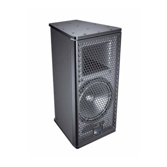
- Page 1 OPERATING INSTRUCTIONS ULTRASERIES UPJunior UltraCompact VariO Loudspeaker ™ ™ Keep these important operating instructions. Check www.meyersound.com for updates.
- Page 2 The contents of this manual are furnished for informational purposes only, are subject to change without notice, and should not be con- strued as a commitment by Meyer Sound Laboratories Inc. Meyer Sound assumes no responsibility or liability for any errors or inaccura- cies that may appear in this manual.
-
Page 3: Important Safety Instructions
2. Keep these instructions. 12. Use only with the caster rails or rigging specified by 3. Heed all warnings. Meyer Sound, or sold with the loudspeaker. Handles are 4. Follow all instructions. for carrying only. 5. Do not use this loudspeaker near water. -
Page 4: Safety Summary
SAFETY SUMMARY ■ ■ English Ne pas installer l’haut-parleur dans un Um ein Überhitzen dem Lautsprecher endroit où il y a de l’eau ou une humid- zu verhindern, das Gerät vor direkter ■ To reduce the risk of electric shock, dis- ité... -
Page 5: Table Of Contents
CONTENTS Chapter 1: Introduction How to Use This Manual Introducing the UPJunior™ Compact VariO™ Loudspeaker Chapter 2: Power Requirements The AC Connectors Power Connector Wiring UPJunior Voltage Requirements UPJunior Current Requirements Electrical Safety Issues Chapter 3: Amplification and Audio Audio Input Modules Chapter 4: Adding Subwoofers to a UPJunior System Adding Subwoofers by Daisy-Chaining Adding Subwoofers with a Line Driver... - Page 6 CONTENTS...
-
Page 7: Chapter 1: Introduction
Information and specifications are subject to change. Updates and supplementary information are available on the ® Meyer Sound website: http://www.meyersound.com Meyer Sound Technical Support is available at: UPJunior Compact VariO Loudspeaker ■ Tel: +1 510 486.1166 The UPJunior’s low-frequency section employs an 8-inch ■... - Page 8 CHAPTER 1: INTRODUCTION UPJuniors with MAAM-UPJunior Array Adapters and Eyebolts UPJunior with MYA-UPJunior Mounting Yoke UPJunior Pole-Mounted with Third-Party Pole Adapter UPJunior Array with MUB-UPJunior U-Bracket, Truss Mounted...
-
Page 9: Chapter 2: Power Requirements
UPJunior AC Input (left) and AC Loop Output (right) Connectors nector for making AC looping cables. Assembled AC loop- ing cables are available from Meyer Sound. The AC Input Connector (Blue) The blue AC Input connector supplies power to the UPJun-... -
Page 10: Upjunior Voltage Requirements
UPJunior loudspeakers require a grounded ify that the voltage is within the required range. If the connection. Always use a grounded outlet and plug. problem persists, contact Meyer Sound Technical It is extremely important that the system be properly Support. -
Page 11: Electrical Safety Issues
UPJUNIOR OPERATING INSTRUCTIONS You can use the following table as a guide for selecting ■ Do not use a ground-lifting adapter or cut the AC cable cable gauges and circuit breaker ratings for the system’s ground pin. operating voltage. UPJunior Current Draw Current Draw 115 V AC 230 V AC... - Page 12 CHAPTER 2: POWER REQUIREMENTS...
-
Page 13: Chapter 3: Amplification And Audio
The low- and high-frequency drivers in the UPJunior are Pin 1 — 220 kOhm to chassis and earth ground (ESD ■ powered by a two-channel proprietary Meyer Sound ampli- clamped) fier with MOSFET output stages. The audio signal is pro- ■... - Page 14 CHAPTER 3: AMPLIFICATION AND AUDIO NOTE: Most source devices are capable of CAUTION: The Limit LEDs indicate when a driving loads no smaller than 10 times their safe, optimum level is exceeded. If a UPJunior output impedance. begins to limit before reaching the required SPL, con- sider adding more loudspeakers to the system.
- Page 15 UPJUNIOR OPERATING INSTRUCTIONS The Looping, Polarity, and Attenuating Audio Input Module (Optional) The Looping, Polarity, and Attenuating Audio Input module has the same input and output connectors and LEDs found on the Looping Audio Input module (see “The Looping Audio Input Module”...
- Page 16 CHAPTER 3: AMPLIFICATION AND AUDIO...
-
Page 17: Chapter 4: Adding Subwoofers To A Upjunior System
A UPJunior loudspeaker system can be deployed with NOTE: If the subwoofer’s Limit LEDs begin to Meyer Sound self-powered subwoofers (see Table 1). Sub- light before reaching the required SPL, con- woofers achieve very low frequency responses and extend sider adding more subwoofers to meet the SPL... -
Page 18: Adding Subwoofers With A Line Driver
GALILEO LOUDSPEAKER MANAGEMENT SYSTEM Using a line driver with dedicated low and mid-hi outputs ® (like Meyer Sound’s LD-1A and LD-2) to drive a UPJunior Meyer Sound’s Galileo loudspeaker management system is loudspeaker system with subwoofers allows adjustments to a comprehensive solution for driving and aligning loud- the gain and polarity of each sub-system. - Page 19 (see “Loop Connector” on page 13). TIP: To address the collective concerns of array design, subwoofer integration, digital signal processors, delay systems, and acoustical condi- tions, a measurement system like Meyer Sound’s SIM 3 is strongly recommended.
- Page 20 CHAPTER 4: ADDING SUBWOOFERS TO A UPJUNIOR SYSTEM...
-
Page 21: Chapter 5: The Vario Horn
32 x 5/8” screws. 2. Carefully remove the grille cover. TIP: To rotate the Meyer Sound logo on the 3. Remove the four 10-32 x 1” flange screws from the horn. UPJunior grille frame, pull up on the logo, rotate 4. - Page 22 CHAPTER 5: THE VARIO HORN...
-
Page 23: Chapter 6: Quickfly Rigging
Up to two UPJuniors, oriented verti- cally, can be suspended with the eyebolts sup- plied by Meyer Sound at a 7:1 safety factor. For this configuration, the top UPJunior would have two eye- bolts installed on its top plate and two eyebolts installed on its bottom plate, for connecting to the second UPJunior. -
Page 24: Pole-Mounting The Upjunior
CHAPTER 6: QUICKFLY RIGGING POLE-MOUNTING THE UPJUNIOR THE MUB-UPJUNIOR U-BRACKET You can mount a single UPJunior on a pole with a third-party You can use the MUB-UPJunior U-bracket to mount a single pole-mount adapter (such as the BMB-200K mounting UPJunior on walls, ceilings, and stage lips, to mount up to bracket from Ultimate Support). - Page 25 UPJUNIOR OPERATING INSTRUCTIONS CAUTION: The 1/4” center holes are not rated Truss-Mounting with the MUB-UPJunior for flown loudspeakers. These holes should An array of UPJuniors (with the MAAM-UPJunior array only be used for pole-mounting with an adapter. adapter) can be mounted on a truss with the MUB-UPJunior U-bracket.
-
Page 26: The Mya-Upjunior Mounting Yoke
CHAPTER 6: QUICKFLY RIGGING Pole-Mounting with the MUB-UPJunior THE MYA-UPJUNIOR MOUNTING YOKE You can use the MUB-UPJunior U-bracket to pole-mount a The MYA-UPJunior mounting yoke suspends a single single UPJunior with a third-party pole adapter. This combi- UPJunior loudspeaker and allows a wide range of horizontal nation allows the UPJunior’s angle to be adjusted. -
Page 27: The Maam-Upjunior Array Adapter
UPJUNIOR OPERATING INSTRUCTIONS THE MAAM-UPJUNIOR ARRAY ADAPTER Arrays are assembled by attaching the array adapter plates to the top and bottom plates of the UPJuniors and securing The MAAM-UPJunior array adapter provides a solid connec- them with the included M8 screws and washers. tion between UPJunior loudspeakers to form horizontal and vertical arrays of up to three loudspeakers. - Page 28 CHAPTER 6: QUICKFLY RIGGING Horizontal Arrays with the MAAM-UPJunior Vertical Arrays with the MAAM-UPJunior Horizontal arrays with the MAAM-UPJunior array adapter Vertical arrays with the MAAM-UPJunior array adapter can can be flown by attaching eyebolts to the UPJunior plates or be flown by attaching eyebolts to the UPJunior plates or directly to the array adapter plates.
- Page 29 UPJUNIOR OPERATING INSTRUCTIONS TIP: To create optimum coverage in a vertical array, the splay between UPJunior loudspeak- ers should be 30° when the VariO horns are in the 80°H x 50°V position (this yields a vertical coverage of 80°). Angles of less than 30° between the loud- speakers can lead to too much interaction between the loudspeakers, while angles of greater than 30°...
- Page 30 CHAPTER 6: QUICKFLY RIGGING...
-
Page 31: Chapter 7: The Rms Remote Monitoring System
Meter views, and Text views that can system) network. RMS allows real-time monitoring of multi- be customized to suit your needs. Loudspeaker data is ple Meyer Sound self-powered loudspeakers from a Win- updated 2–5 times per second. Individual loudspeakers can dows-based computer. The RMS host computer... -
Page 32: The Rms Module
The RMS module is installed in the bottom slot of the user Pressing the Reset button causes the RMS module’s firm- panel on the back of the Meyer Sound loudspeaker. The ware to reboot; this will not affect whether the loudspeaker RMS user panel has three LEDs, two buttons, and two Net- is commissioned (which is stored in flash memory). -
Page 33: Chapter 8: System Design And Integration Tools
Online Pro, Meyer Sound’s patented online acoustical pre- are based on 360 1/48th-octave-band measurements taken diction tool, and SIM 3, a comprehensive system for mea- with a SIM audio analyzer in the Meyer Sound anechoic surement and analysis. chamber. The extraordinary consistency between Meyer... -
Page 34: The Sim ® 3 Measurement System
The MAPP Online Pro client software is regularly upgraded ■ Measuring propagation delays between subsystems to to add support for the latest Meyer Sound loudspeakers, as determine appropriate polarities and delay times well as to add feature enhancements. Most upgrades are Measuring variations in frequency response caused by ■... -
Page 35: Appendix A: Installing The Optional Rain Hoods
APPENDIX A: INSTALLING THE OPTIONAL RAIN HOODS The optional UPJunior rain hoods provide all-weather pro- INSTALLING THE HORIZONTAL RAIN HOOD tection for its user panel and connectors in fixed, outdoor To install the UPJunior horizontal rain hood: installations. The rain hood is available in both vertical 1. - Page 36 APPENDIX A: INSTALLING THE OPTIONAL RAIN HOODS...
-
Page 37: Appendix B: Basic Troubleshooting
This section includes some basic troubleshooting sugges- Hum or noise can be produced by a ground loop. Since ■ tions for configuring your Meyer Sound loudspeaker. the UPJunior is effectively ground-lifted, the loop may be broken elsewhere in the system. - Page 38 APPENDIX B: BASIC TROUBLESHOOTING ■ Connect the audio source to another loudspeaker to ver- ify the signal is full-range. Turn the source level down before reconnecting the audio source and increase the level slowly to avoid a sudden blast of sound. ■...
-
Page 39: Appendix C: Upjunior Specifications
APPENDIX C: UPJUNIOR SPECIFICATIONS ACOUSTICAL Operating Frequency 70 Hz – 20 kHz Range Note: Recommended maximum operating frequency range. Response depends on loading conditions and room acoustics. Frequency Response 76 Hz – 18 kHz ±4 dB Note: Measured free field with 1/3 octave frequency resolution at 4 meters. Phase Response 250 Hz –... - Page 40 APPENDIX C: UPJUNIOR SPECIFICATIONS RF Filter Common mode: 425 kHz Differential mode: 142 kHz TIM Filter <80 kHz, integral to signal processing Nominal Input Sensi- 0 dBV (1 V rms, 1.4 V peak) continuous average is typically the onset of limiting for tivity noise and music Audio source must be capable of producing +20 dBV (10 V rms, 14 V peak) into 600 Ω...
- Page 41 UPJUNIOR OPERATING INSTRUCTIONS UPJunior Dimensions...
- Page 42 APPENDIX C: UPJUNIOR SPECIFICATIONS...
- Page 44 Meyer Sound Laboratories Inc. 2832 San Pablo Avenue Berkeley, CA 94702 © 2007 www.meyersound.com Meyer Sound Laboratories Inc. T: +1 510 486.1166 05.173.005.01 A F: +1 510 486.8356...
Need help?
Do you have a question about the UPJunior UltraCompact VariO and is the answer not in the manual?
Questions and answers