
Related Manuals for Meyer Sound UPQ-1P


Summary of Contents for Meyer Sound UPQ-1P
- Page 1 OPERATING INSTRUCTIONS ULTRASERIES UPQ-1P Wide Coverage Loudspeaker Keep these important operating instructions. Check www.meyersound.com for updates.
- Page 2 The contents of this manual are furnished for informational purposes only, are subject to change without notice, and should not be con- strued as a commitment by Meyer Sound Laboratories Inc. Meyer Sound assumes no responsibility or liability for any errors or inaccura- cies that may appear in this manual.
-
Page 3: Important Safety Instructions
2. Keep these instructions. 12. Use only with the caster rails or rigging specified by 3. Heed all warnings. Meyer Sound, or sold with the loudspeaker. Handles are 4. Follow all instructions. for carrying only. 5. Do not use this loudspeaker near water. -
Page 4: Safety Summary
SAFETY SUMMARY English Ne pas installer l’haut-parleur dans un Um ein Überhitzen dem Lautsprecher endroit où il y a de l’eau ou une humidi- zu verhindern, das Gerät vor direkter To reduce the risk of electric shock, dis- té excessive. Sonneneinstrahlung fernhalten und connect the loudspeaker from the AC nicht in der Nähe von wärmeabstrahlen-... -
Page 5: Table Of Contents
Electrical Safety Issues Chapter 3: Amplification and Audio VEAM Cabling Audio Input Modules Chapter 4: Adding Subwoofers to a UPQ-1P Loudspeaker System Adding Subwoofers by Daisy-Chaining Adding Subwoofers with a Line Driver Galileo Loudspeaker Management System Using Digital Signal Processors... -
Page 7: Chapter 1: Introduction
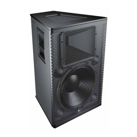
CHAPTER 1: INTRODUCTION HOW TO USE THIS MANUAL INTRODUCING THE UPQ-1P LOUDSPEAKER Make sure to read these operating instructions in their The self-powered UPQ-1P wide coverage loudspeaker is a entirety before configuring a loudspeaker system with member of the popular UltraSeries ®... -
Page 8: Advanced Upq Technology
CHAPTER 1: INTRODUCTION The UPQ-1P is designed to be used as the main system in The UPQ-1P loudspeaker’s on-board amplifier delivers 1275 small to mid-sized venues or integrate smoothly and easily watts total burst power (2550 watts peak). The convection- with other Meyer Sound products as centerfill or sidefills in cooled amplifier utilizes Meyer Sound’s proprietary Quiet-... -
Page 9: Rig-Ready
UPQ-1P OPERATING INSTRUCTIONS RIG-READY The durable trapezoidal enclosure of the UPQ-1P loud- speaker has a textured, hard-shell black finish and includes an integral pole mount receptacle that accepts 1-1/2” poles or speaker stands. UPQ-1P Suspended from an MPA-UPQ UPQ-1P Pole Mount Receptacle In addition, the cabinet includes versatile rigging end plates. -
Page 10: Total System Approach
The 600-HP High-Power Subwoofer quickly determine the coverage, frequency response, impulse response, and maximum output of Meyer In addition, the UPQ-1P loudspeaker can be used in combi- Sound loudspeakers, and provides useful rigging nation with other Meyer Sound subwoofers, such as the information. -
Page 11: Chapter 2: Power Requirements
The UPQ-1P loudspeaker combines advanced loudspeaker THE AC CONNECTORS technology with equally advanced power capabilities. The user panel on the back of the UPQ-1P loudspeaker Understanding power distribution, voltage and current includes the following AC connectors: requirements, as well as electrical safety issues, is critical to the safe operation of the UPQ-1P loudspeaker. -
Page 12: Power Connector Wiring
Do not ground-lift the AC rating of the AC power cable connected to the first UPQ-1P. cable. Number of UPQs that Can Be Looped with AC Power... -
Page 13: Upq-1P Current Requirements
6.0 A peak 8.4 A peak 7.1 A peak The current draw for the UPQ-1P loudspeaker is dynamic and fluctuates as operating levels change. Since different The minimum electrical service amperage required by a cables and circuit breakers heat up at varying rates, it is... - Page 14 Make sure the AC power cable for the UPQ-1P loud- speaker has the appropriate power plug (on the other end) for the area in which you will operate the loud- speaker.
-
Page 15: Chapter 3: Amplification And Audio
Pin 2 — Signal (+) The user panel on the back of the UPQ-1P loudspeaker has Pin 3 — Signal (–) two slots for modules. The top slot contains an audio input Case —... - Page 16 Increases to the input level have no effect. ers, divide 10 kOhms (the input impedance for a single Distortion increases due to clipping and nonlinear driver UPQ-1P) by the number of looped loudspeakers. For exam- operation. ple, the load impedance for 10 UPQ-1P loudspeakers is 1000 ohms (10 kOhms / 10).
- Page 17 0 dB (no attenuation), when turned all the way CAUTION: The heatsink for the UPQ-1P loud- to the right, to –18 db, when turned all the way to the left. speaker can reach temperatures of up to 85° C The Attenuator knob does not affect the signal coming from (185°...
- Page 18 CHAPTER 3: AMPLIFICATION AND AUDIO...
-
Page 19: Chapter 4: Adding Subwoofers To A Upq-1P Loudspeaker System
Input of the first UPQ-1P, then connect the ±4 dB 2 x 1 for flat frequency response Loop output of the first UPQ-1P to the Input of the sec- ond UPQ-1P (and so forth). Full-range signals can be connected directly to Meyer 2. -
Page 20: Adding Subwoofers With A Line Driver
1. Daisy-chain the suggested number of UPQ loudspeakers lyzer. for your subwoofer (see Table 2). Connect the output of the line driver to the Input of the first UPQ-1P, then con- nect the Loop output of the first UPQ-1P to the Input of USING DIGITAL SIGNAL PROCESSORS the second (and so forth). - Page 21 UPQ-1P OPERATING INSTRUCTIONS In addition, when using third-party digital signal processors to filter source signals, it is highly recommended that the fil- ter be configured to emulate the low-cut filter used by Meyer Sound’s LD-1A and LD-2. LD-1A and LD-2 Low-Cut Filter Parameters...
- Page 22 CHAPTER 4: ADDING SUBWOOFERS TO A UPQ-1P LOUDSPEAKER SYSTEM...
-
Page 23: Chapter 5: Quickfly Rigging
The UPQ-1P loudspeaker is compatible with Meyer Sound’s BASIC EYEBOLT RIGGING QuickFly system, a comprehensive collection of custom- The UPQ-1P loudspeaker ships with two M10 threaded, 25 designed rigging, flying, and mounting options. Comprised mm eyebolts, which attach to the top or bottom of the loud- of rugged, reliable, and easy-to-configure components, speakers and can be used to suspend them. -
Page 24: Pole-Mounting The Upq-1P
CHAPTER 5: QUICKFLY RIGGING POLE-MOUNTING THE UPQ-1P THE MYA-UPQ MOUNTING YOKE You can mount a single UPQ-1P loudspeaker on a heavy- The MYA-UPQ (PN 40.185.052.01) mounting yoke suspends duty loudspeaker stand with standard a 1-1/2” pole using its a single UPQ-1P loudspeaker and allows a wide range of integral pole mount receptacle. -
Page 25: The Mpa-Upq Array Adapter
UPQ-1P loudspeakers; two kits are required for an array of three loudspeakers. Arrays are assembled by attaching the array adapter plates to the top and bottom plates of the UPQ-1P and securing them with the included M10 knobs and washers. CAUTION:... - Page 26 Two MPA-UPQ array adapter plate can be used to suspend plates on the tops and bottoms of the loudspeakers a single UPQ-1P loudspeaker horizontally. The adapter between each loudspeaker. The adapter plates are oriented plates attach to the top and bottom edges of the loud- with the middle shackle row in.
- Page 27 MPA-UPQ Splay Angles for Arrayed Loudspeakers The MPA-UPQ array adapter plate has six different M10 screw holes for adjusting the splay angle for arrayed UPQ-1P loudspeakers. The following illustrations show the possible splay angles for arrayed loudspeakers. 42° 50° MPA-UPQ with Loudspeakers Arrayed at 42°...
- Page 28 CHAPTER 5: QUICKFLY RIGGING...
-
Page 29: Chapter 6: The Rms Remote Monitoring System
CHAPTER 6: THE RMS REMOTE MONITORING SYSTEM An optional RMS remote monitoring system module can be THE RMS SOFTWARE installed in the UPQ-1P loudspeaker, allowing the loud- The optional RMS software provides extensive system sta- speakers to be connected to an RMS network. RMS allows... -
Page 30: The Rms Module
The RMS module is installed in the bottom slot of the user Pressing the Reset button causes the RMS module’s firm- panel on the back of the Meyer Sound loudspeaker. The ware to reboot; this will not affect whether the loudspeaker RMS user panel has three LEDs, two buttons, and two Net- is commissioned (which is stored in flash memory). -
Page 31: Chapter 7: System Design And Integration Tools
Online Pro, Meyer Sound’s patented online acoustical pre- are based on 360 1/48th-octave-band measurements taken diction tool, and SIM 3, a comprehensive system for mea- with a SIM audio analyzer in the Meyer Sound anechoic surement and analysis. chamber. The extraordinary consistency between Meyer... -
Page 32: The Sim 3 Measurement System
The MAPP Online Pro client software is regularly upgraded Measuring propagation delays between subsystems to to add support for the latest Meyer Sound loudspeakers, as determine appropriate polarities and delay times well as to add feature enhancements. Most upgrades are... -
Page 33: Appendix A: Optional Veam Multipin Connector
APPENDIX A: OPTIONAL VEAM MULTIPIN CONNECTOR The UPQ-1P loudspeaker requires a grounded outlet. It is For complete wiring conventions and pin-outs for AC, audio, very important that the system be properly grounded in and RMS connections, refer to the Meyer Sound document order to operate safely and properly. - Page 34 APPENDIX A: OPTIONAL VEAM MULTIPIN CONNECTOR...
-
Page 35: Appendix B: Upq-1P Specifications
APPENDIX B: UPQ-1P SPECIFICATIONS ACOUSTICAL Operating Frequency 55 Hz – 18 kHz Range Note: Recommended maximum operating frequency range. Response depends on loading conditions and room acoustics. Frequency Response 60 Hz – 16 kHz ±4 dB Note: Measured free field with 1/3 octave frequency resolution at 4 meters. - Page 36 APPENDIX B: UPQ-1P SPECIFICATIONS TIM Filter <80 kHz, integral to signal processing Nominal Input Sensi- 0 dBV (1 V rms, 1.4 V peak) continuous average is typically the onset of limiting for tivity noise and music Audio source must be capable of producing +20 dBV (10 V rms, 14 V peak) into 600 Ω...
- Page 37 UPQ-1P OPERATING INSTRUCTIONS Dimensions 19.00" w x 28.27" h x 18.18" d (483 mm x 718 mm x 462 mm) Weight Weight 108 lbs (49 kg) 34° 19.00 18.18 [483 mm] [462 mm] 8.43 28.27 [214 mm] [718 mm] 13.50 [343 mm] 8.11...
- Page 38 APPENDIX B: UPQ-1P SPECIFICATIONS...
- Page 40 Meyer Sound Laboratories Inc. 2832 San Pablo Avenue Berkeley, CA 94702 © 2008 Meyer Sound Laboratories Inc. www.meyersound.com 05.185.005.01 A2 T: +1 510 486.1166...
Need help?
Do you have a question about the UPQ-1P and is the answer not in the manual?
Questions and answers