Sign In
Upload
Download
Table of Contents
Contents
Add to my manuals
Delete from my manuals
Share
URL of this page:
HTML Link:
Bookmark this page
Add
Manual will be automatically added to "My Manuals"
Print this page
×
Bookmark added
×
Added to my manuals
Manuals
Brands
Meyer Sound Manuals
Speakers
UPQ-D Series
Operating instructions manual
Meyer Sound UPQ-D Series Operating Instructions Manual
Wide/narrow/wide symmetrical coverage loudspeaker
Hide thumbs
1
2
3
4
5
6
Table Of Contents
7
8
9
10
11
12
13
14
15
16
17
18
19
20
21
22
23
24
25
26
27
28
29
30
31
32
33
34
35
36
37
38
39
40
41
42
43
44
45
46
47
48
page
of
48
Go
/
48
Contents
Table of Contents
Bookmarks
Table of Contents
Important Safety Instructions
Table of Contents
Chapter 1: Introduction
How to Use this Manual
The UPQ-D Series Loudspeaker
Integrated Amplifier and Processing
Rig-Ready
Total System Approach
Chapter 2: Power Requirements
AC Power Distribution
AC Connectors
Wiring AC Power Cables
Voltage Requirements
Current Requirements
Intelligent AC Power Supply
Electrical Safety Guidelines
Chapter 3: Amplification and Audio Connectors
Audio Connectors
Trupower Limiting
On/Status LED
Amplifier Cooling System
Chapter 4: Adding Low Frequency Control
Adding Subwoofers by Daisy-Chaining
Using a Processor
Chapter 5: Quickfly Rigging
Important Safety Considerations
Basic Eye Bolt Rigging
UPQ-D Series Rigging Accessories
Pole-Mounting the UPQ-D Series
The MYA-UPQ Mounting Yoke
The MPA-UPQ Array Adapter
Chapter 6: RMS Remote Monitoring System
Compass Control Software
RMS Module
Neuron ID for RMS Module
Resetting the RMS Module
Chapter 7: System Design and Integration Tools
MAPP System Design Tool
Galileo Galaxy Network Platform
SIM Measurement System
Appendix A: Meyer Sound Weather Protection
Weather Protection Components
Installation Practices
IP Ratings
Appendix B: Rain Hoods
Rigid Rain Hood
Foldable Rain Hood
Appendix C: UPQ-D Series Specifications
UPQ-D Series Acoustical, Electrical, and Physical Specifications
UPQ-D1/D2/D3 Loudspeaker Dimensions
UPQ-D1/D2/D3 with Rain Hood Loudspeaker Dimensions
Advertisement
Quick Links
1
The Upq-D Series Loudspeaker
2
Voltage Requirements
3
Audio Connectors
4
On/Status Led
5
Upq-D Series Acoustical, Electrical, and Physical Specifications
6
Upq-D1/D2/D3 Loudspeaker Dimensions
Download this manual
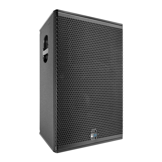
OPERATING INSTRUCTIONS
ULTRA
UPQ-D1 Wide Coverage Loudspeaker
UPQ-D2 Narrow Coverage Loudspeaker
UPQ-D3 Wide Symmetrical Coverage Loudspeaker
Keep these important operating instructions.
Check www.meyersound.com for updates.
Table of
Contents
Previous
Page
Next
Page
1
2
3
4
5
Advertisement
Table of Contents
Need help?
Do you have a question about the UPQ-D Series and is the answer not in the manual?
Ask a question
Questions and answers
Related Manuals for Meyer Sound UPQ-D Series
Speakers Meyer Sound UPQ-1P Operating Instructions Manual
Wide coverage (40 pages)
Speakers Meyer Sound UPQ-D1 Operating Instructions Manual
Wide/narrow/wide symmetrical coverage loudspeaker (48 pages)
Speakers Meyer Sound UPQ-D2 Operating Instructions Manual
Wide/narrow/wide symmetrical coverage loudspeaker (48 pages)
Speakers Meyer Sound UPQ-D3 Operating Instructions Manual
Wide/narrow/wide symmetrical coverage loudspeaker (48 pages)
Speakers Meyer Sound UPA-1P Operating Instructions Manual
Upa-p series self-powered loudspeakers (16 pages)
Speakers Meyer Sound UPA-2P Operating Instructions Manual
Upa-p series self-powered loudspeakers (16 pages)
Speakers Meyer Sound Compact VariO UPJ-1P Operating Instructions Manual
Ultraseries compact vario loudspeaker (32 pages)
Speakers Meyer Sound UPJunior Brochure & Specs
Ultracompact vario loudspeaker (12 pages)
Speakers Meyer Sound UPM-1P Operating Instructions Manual
Ultra series ultra-compact wide coverage loudspeaker and ultra-compact narrow coverage loudspeaker (36 pages)
Speakers Meyer Sound UPM-1P Operating Instructions Manual
Ultra series ultra-compact wide coverage loudspeaker/ ultra-compact narrow coverage loudspeaker (36 pages)
Speakers Meyer Sound UP-4XP Operating Instructions Manual
Ultra series ultracompact loudspeaker (40 pages)
Speakers Meyer Sound UPJunior UltraCompact VariO Operating Instructions Manual
Ultraseries (44 pages)
Speakers Meyer Sound MILO 60 Datasheet
High-power narrow coverage curvilinear array loudspeaker m series (2 pages)
Speakers Meyer Sound UPA-1P Specification Sheet
Self-powered reinforcement loudspeaker (2 pages)
Speakers Meyer Sound Reinforcement Loudspeaker MSL-3A Specifications
Reinforcement loudspeaker (4 pages)
Speakers Meyer Sound Stella 8c Product Information
Industrial series ceiling mount installation loudspeaker (1 page)
This manual is also suitable for:
Upq-d1
Upq-d2
Upq-d3
Table of Contents
Print
Rename the bookmark
Delete bookmark?
Delete from my manuals?
Login
Sign In
OR
Sign in with Facebook
Sign in with Google
Upload manual
Upload from disk
Upload from URL


Need help?
Do you have a question about the UPQ-D Series and is the answer not in the manual?
Questions and answers