
Subscribe to Our Youtube Channel
Related Manuals for Netstor NR760A


Summary of Contents for Netstor NR760A
-
Page 1: User Manual
Netstor NR760A / NR340A / NR330A iSCSI GbE to SATA II RAID Storage User Manual Version 2.0 (Jan, 2010) - 1 -... -
Page 2: About This Manual
Preface About this manual This manual is the introduction of Netstor’s NR760A / NR340A / NR330A iSCSI GbE Raid Storage Solution and it aims to help users know the operations of the disk array system easily. Information contained in this... -
Page 3: Disk Installation
4. Fan Status LED Normal – Green; Fail – Red (too slow rpm or stop) 5. LCM 6. Back (Control button) 7. Up (Control button) 8. Enter (Control button) 9. Down (Control button) 10. HDD Power LED 11. HDD Status LED 12. - Page 4 1. Connect CH0, CH1 to GbE switching ports for data transmission. 2.. Connect RJ45 to Ethernet port for management. - 4 -...
-
Page 5: Table Of Contents
Table of Contents Features ................7 Terminology ..............8 RAID levels ..............10 Volume relationship diagram.......... 12 Chapter 2 Getting started ..........13 Before starting ..............13 iSCSI introduction ............13 Management methods ........... 15 2.3.1 Web GUI ..................16 2.3.2 Remote control –... - Page 6 Volume configuration ............. 39 3.6.1 Physical disk ................... 40 3.6.2 Volume group ................. 43 3.6.3 User data volume ................45 3.6.4 Cache volume ................47 3.6.5 Logical unit number ................ 48 3.6.6 Example ..................50 Enclosure management ..........60 3.7.1 SES configuration ................
-
Page 7: Features
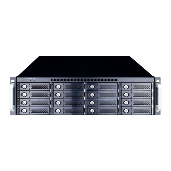
Chapter 1 RAID introduction 1.1 Features Netstor iSCSI series is a high-performance RAID solution including the following Models NR760A: Desktop 8 bay iSCSI(Host) to SATA II(Disk) Raid Storage NR340A: 2U-8 bay iSCSI(Host) to SATA II(Disk) Raid Storage NR330A: 3U-16 bay iSCSI(Host) to SATA II(Disk) Raid Storage Netstor iSCSI storage solution features: Front-end 2 ports GbE NIC ports with load-balancing &... -
Page 8: Terminology
Netstor’s iSCSI solution is the most cost-effective disk array controller with completely integrated high-performance and data-protection capabilities which meet or exceed the highest industry standards, and the best data solution for small/medium business (SMB) users. 1.2 Terminology The document uses the following terms: RAID is the abbreviation of “Redundant Array of Independent... - Page 9 One 4-disk RAID 0 volume: RAID width= 4; RAID RAID row (RAID cell in copy=1; RAID row=1. one row) One 3-way mirroring volume: RAID width=1; RAID copy=3; RAID row=1. One RAID 10 volume over 3 4-disk RAID 1 volume: RAID width=1; RAID copy=4; RAID row=3. Write-Through cache-write policy.
-
Page 10: Raid Levels
read and write requests to its virtual disks. SCSI Small Computer Systems Interface. iSCSI Internet Small Computer Systems Interface. Self-Monitoring Analysis and Reporting Technology. S.M.A.R.T. World Wide Name. Host Bus Adapter. SAF-TE SCSI Accessed Fault-Tolerant Enclosures. Network Interface Card. LACP Link Aggregation Control Protocol. - Page 11 Disk mirroring over two disks. RAID 1 needs at least two hard RAID 1 drives. Extension to RAID 1 level. It has N copies of the disk. N-way mirror Striping with parity on the dedicated disk. RAID 3 needs at RAID 3 least three hard drives.
-
Page 12: Volume Relationship Diagram
PD 3 Figure 1.4.1 This is the volume structure of Netstor designed. It describes the relationship of RAID components. One VG (Volume Group) consists of a set of UDVs (User Data Volume) and owns one RAID level attribute. Each VG can be divided into several UDVs. -
Page 13: Chapter 2 Getting Started
CHAP security information, including CHAP username and password. (optional) Setup the hardware connection before power on servers and Netstor iSCSI storage. Connect console cable, management port cable, and iSCSI data port cables in advance. 2.2 iSCSI introduction iSCSI (Internet SCSI) is a protocol which encapsulates SCSI (Small Computer System Interface) commands and data in TCP/IP packets for linking storage devices with servers over common IP infrastructures. - Page 14 number of storage volumes by using iSCSI over TCP/IP networks. IP SANs can scale the storage capacity with any type and brand of storage system. In addition, it can be used by any type of network (Ethernet, Fast Ethernet, and Gigabit Ethernet) and combination of operating systems (Microsoft Windows, Linux, Solaris, etc.) within the SAN network.
-
Page 15: Management Methods
(sfnet) and Open-iSCSI projects merged in April 11, 2005. http://www.open-iscsi.org/ Open-iSCSI website: http://www.open-iscsi.org/docs/README Open-iSCSI README: Google groups: http://groups.google.com/group/open-iscsi/threads?gvc=2 http://groups.google.com/group/open-iscsi/topics ATTO iSCSI initiator is available for Mac. http://www.attotech.com/xtend.html Website: 2.3 Management methods There are three management methods to manage Netstor iSCSI storage, described in the following: - 15 -... -
Page 16: Web Gui
2.3.1 Web GUI Netstor iSCSI storage support graphic user interface(GUI) to manage the system. Be sure to connect LAN cable. The default setting of management port IP is DHCP and DHCP address displays on LCM; user can inspect LCM for IP first, then open the browser and type the DHCP address: (The DHCP address is dynamic and user may need to check every time after reboot.) -
Page 17: Enclosure
Netstor iSCSI storage only support SSH for remote control. For using SSH, the IP address and password are required for 2.4 Enclosure 2.4.1 There are four buttons to control Netstor LCM (LCD Control Module), including: (up), (down), ESC (Escape), and ENT (Enter). - Page 18 Quick Install Quick steps to create a volume. Please refer to next chapter for operation in web UI. View IP Setting Display current IP address, subnet mask, and gateway. Set IP address, subnet mask, and gateway. There are 2 Change IP options: DHCP (Get IP address from DHCP server) or Config static IP.
- Page 19 RAID 5 RAID 6 [Apply The [ Yes RAID 0+1 Config] No ] xxx GB [IP Config] [Static IP] [IP Address] Netstor [192.168.1.1] [View IP Setting] Technology [IP Subnet Mask] [255.255.255.0] [IP Gateway] [192.168.010.254] [ Yes [DHCP] No ] Adjust IP...
-
Page 20: System Buzzer
2.4.2 System buzzer The system buzzer features are listed below: The system buzzer alarms 1 second when system boots up successfully. The system buzzer alarms continuously when there is an error occurred. The alarm will be stopped after the error is cleared or the alarm is muted. - Page 21 GREEN Management port LED: transmit/receive indication. ORANGE LED is for LAN port 10/100 LINK indication. BUSY LED: Hardware activated LED when the front-end channel is busy. POWER LED: Hardware activated LED when system is powered on. - 21 -...
-
Page 22: Chapter 3 Web Gui Guideline
Chapter 3 Web GUI guideline 3.1 Web GUI hierarchy The below table is the hierarchy of web GUI. Step 1 / Step 2 / Step 3 / Confirm Quick Install System Config System name System name DHCP / Static / Address / Mask / Gateway / DNS / IP address HTTP port / HTTPS port / SSH port Language... -
Page 23: Login
Sure to logout? Logout 3.2 Login Netstor iSCSI storage supports graphic user interface (GUI) to operate the system. Be sure to connect the LAN cable. The default IP setting is DHCP; open the browser and enter: http://192.168.xx.xx (Please check the DHCP address first on LCM.) Click any function at the first time;... - Page 24 After login, you can choose the functions which lists on the left side of window to setup configuration. Figure 3.2.1 There are four indicators at the top-right corner. Figure 3.2.2 RAID light: Green means RAID works well. Red represents RAID failure. Temperature light: Green means normal temperature.
-
Page 25: Quick Install
Biggest capacity of RAID level for user to choose. The fewest disk number for RAID level / volume size. E.g., user chooses RAID 5 and the Netstor iSCSI Storage has 12*200G + 4*80G HDDs inserted. If we use all 16 HDDs for a RAID 5, and then the maximum size of volume is 1200G (80G*15). -
Page 26: System Configuration
Figure 3.3.1 Step 2: Please select a LUN number. Access control of host would show as a wildcard “*”, which means every host can access to this volume. In this page, the “Volume size” can be changed. Default value is the maximum volume size. -
Page 27: System Name
Figure 3.4.1 3.4.1 System name “System name” allows users change system name. Default “system name” composed of model name and serial number of this system, e.g.: P200C- A00001. Figure 3.4.1.1 3.4.2 IP address “IP address” allows users change IP address for remote administration. There are 2 options, DHCP (Get IP address from DHCP server) or static IP. -
Page 28: Language
port number when the default port number is not allowed on host/server. Figure 3.4.2.1 3.4.3 Language “Language” allows users set the language shown in Web UI. The option “Auto Detect” will set language setting by browser’s language setting. Figure 3.4.3.1 3.4.4 Login config “Login config”... -
Page 29: Password
Auto logout: The options are (1) Disable; (2) 5 minutes; (3) 30 minutes; (4) 1 hour. The system will log out automatically when user idled for a specific period of time. Login lock: Disable/Enable. When the login lock is enabled, the system allows only one user to login or modify system settings. -
Page 30: Mail
Figure 3.4.6.1 3.4.7 Mail “Mail” allows users set 3 mail addresses at most to receive the event notification. Some mail servers would check “Mail-from address” and need authentication for anti-spam. Please fill the necessary fields and click “Send test mail” to test whether email functions are available. User can also select which level of event logs are needed to be sent via Mail. -
Page 31: Snmp
Figure 3.4.7.1 3.4.8 SNMP “SNMP” allows users set up SNMP trap for alerting via SNMP. It allows up to 3 SNMP trap addresses. Default community setting is “public”. User can choose the event log level and default setting only enables INFO event log in SNMP. -
Page 32: Messenger
There are many SNMP tools. The following web sites are for your reference: SNMPc: http://www.snmpc.com/ Net-SNMP: http://net-snmp.sourceforge.net/ 3.4.9 Messenger Using “Messenger”, user must enable the service “Messenger” in Windows (Start Control Panel Administrative Tools Services Messenger), and then event logs can be received. It allows up to 3 messenger addresses. User can choose the event log levels and default setting enables the WARNING and ERROR event logs. -
Page 33: Event Log
Figure 3.4.10.1 There are some syslog server tools. The following web sites are for your reference: WinSyslog: http://www.winsyslog.com/ Kiwi Syslog Daemon: http://www.kiwisyslog.com/ Most UNIX systems build in syslog daemon. 3.4.11 Event log “Event log” can view the event messages. Click “Filter” button to choose the level of event log display. -
Page 34: Iscsi Config
The event logs are actually saved in the first four hard drives; each hard drive has one copy of event log. For one set of Netstor iSCSI Storage, there are four copies of event logs to make sure users can check event log any time when there is/are failed disk(s). -
Page 35: Entity Property
“NIC” allows users change IP addresses of iSCSI data ports. NR760A / NR340A / NR330A has two gigabit LAN ports to transmit data. Figure 3.5.2.2 Figure 3.5.2.3 (Figure 3.5.2.3: NR760A/NR340A/NR330A, there are 2 iSCSI data ports. Each of them is set to static IP.) - 35 -... -
Page 36: Node
The MTU size of switching hub and HBA on host must be enabled. Otherwise, the LAN connection can not work properly. 3.5.3 Node “Node” allows users view the target name for iSCSI initiator. NR760A / NR340A / NR330A supports single-node. The node name exists by default. - 36 -... - Page 37 CHAP enables the username and password to transmitting in an encrypted form for protection. To use CHAP authentication in NR760A / NR340A / NR330A, please follow the procedures. Click “...
-
Page 38: Session
Tips After setting CHAP, the initiator in host/server should be set the 3.5.4 Session “Session” can display iSCSI session and connection information, including the following items: 1. Host (Initiator Name) 2. Error Recovery Level 3. Error Recovery Count 4. Detail of Authentication status and Source IP: port number. Figure 3.5.4.1 (Figure 3.5.4.1: iSCSI Session.) Clicking the button “... -
Page 39: Chap Account
Enter “User”, “Secret”, and “Confirm” secret again. Figure 3.5.5.3 Click “ ”. Figure 3.5.5.4 (Figure 3.5.5.4: Netstor iSCSI Storage, create a CHAP account named “chap1”.) Click “ ” to delete CHAP account. 3.6 Volume configuration “Volume config” is designed for setting up the volume configurations... -
Page 40: Physical Disk
including “Physical disk”, “Volume group”, “User data volume”, “Cache volume”, and “Logical unit”. Figure 3.6.1 3.6.1 Physical disk “Physical disk” to view the status of hard drives in the system. The following are operation tips: Multiple selection. Select one or more checkboxes in front of the slot number. - Page 41 Figure 3.6.1.1 (Figure 3.6.1.1: Physical disks of slot 1,2,3,4 are created for a VG named “VG-R0”. Physical disks of slot 6,7,8,9 are created for a VG named “VG-R6”. Slot 11 is set as dedicated spare disk of VG named “VG-R6”. The others are free disks.) •...
- Page 42 Capacity of hard drive. Size (GB) Related volume group name. VG Name The status of hard drive. Status the hard drive is good. “GOOD” the hard drive has the bad blocks. “DEFECT” the hard drive cannot work in the “FAIL” respective volume.
-
Page 43: Volume Group
Dedicated spares Set hard drive(s) to dedicated spare of selected VGs. In this page, Netstor ISCSI Storage also provides HDD auto spindown down to save power. The default setting is disabled. User can set up in physical disk page, too. - Page 44 • VG column description: Figure 3.6.2.1 (Figure 3.6.2.1: There is a RAID 0 with 4 physical disks, named “VG-R0”, total size is 297GB, free size is 267GB, related to 1 UDV. Another is a RAID 6 with 4 physical disks, named “VG-R6”.) Number of volume group.
-
Page 45: User Data Volume
disk or disk failure. Rebuild. This volume group is doing Status 2 “R” rebuilding. Migration. This volume group is doing Status 3 “M” migration. The RAID level of the volume group. The button next RAID to the RAID level is “Migrate”. Click “Migrate” can add disk(s) to do expansion or change the RAID level of the Volume group. - Page 46 (Figure 3.6.3.1: Create a UDV named “UDV-01”, related to “VG-R0”, size is 30GB, status is online, write back, high priority, related to 1 LUN, with cache volume 663MB. The other UDV is named “UDV-02”, initializing to 46%. • UDV column description: Number of user data volume.
-
Page 47: Cache Volume
Ratio of initializing or rebuilding. The levels of RAID that user data volume is using. RAID Number of LUN(s) that user data volume is #LUN attaching. The VG name of the user data volume. VG name The cache volume of the user data volume. CV (MB) •... -
Page 48: Logical Unit Number
• CV column description: Number of the Cache volume. The button next to the CV No. is “More Information”. It shows the details of the cache volume. Total capacity of the cache volume The button next Size(MB) to the CV size is “Resize”. The CV size can be adjusted. - Page 49 enter an initiator node name for access control, or fill-in wildcard “*”, which means every host can access the volume. Choose LUN number and permission, then click “ ”. Figure 3.6.5.1 Figure 3.6.5.2 (Figure 3.6.5.2: UDV-01 is attached to LUN 0 and every host can access. UDV-02 is attached to LUN 1 and only initiator note named “iqn.1991-05.com.microsoft:demo”...
-
Page 50: Example
3.6.6 Example The followings are examples of creating volumes. Example 1 is to create two UDVs sharing the same CV (global cache volume) and set a global spare disk. Example 2 is to create two UDVs. One shares the global cache volume, and the other uses dedicated cache volume. - Page 51 Figure 3.6.6.2 (Figure 3.6.6.2: Creating a RAID 5 with 4 physical disks, named “VG-R5”. The total size is 114GB. Because there is no related UDV, free size still remains 114GB.) Step 2: Create UDV (User Data Volume). To create a user data volume, please follow the procedures. Figure 3.6.6.3 Select “/ Volume config / User data volume”.
- Page 52 Figure 3.6.6.4 (Figure 3.6.6.4: Create UDVs named “UDV-R5-1” and “UDV-R5-2”. Regarding to “VG- R5”, the size of “UDV-R5-1” is 50GB, the size of “UDV-R5-2” is 64GB. The status of these UDVs are online, write back, high priority with cache volume 120MB. “UDV-R5-1” is initialing about 4%.
- Page 53 “ ”. Done. Figure 3.6.6.6 (Figure 3.6.6.6: UDV-R5-1 is attached to LUN 0 and any hosts can access. UDV-R5-2 is attached to LUN 1 and only initiator note named “iqn.1991-05.com.microsoft:demo” can access.) Tips The matching rules of access control are from top to bottom in sequence.
- Page 54 Figure 3.6.6.7 (Figure 3.6.6.7: Slot 5 is set as global spare disk.) Step 5: Done. They can be used as iSCSI disks. Delete UDVs, VG, please follow the steps listed below. Step 6: Detach LUN from UDV. In “/ Volume config / Logical unit”, Figure 3.6.6.8 Select LUNs by clicking the checkbox in the row, and then click “...
- Page 55 Step 7: Delete UDV (User Data Volume). To delete the user data volume, please follow the procedures: Select “/ Volume config / User data volume”. Select UDVs by clicking the checkbox in the row. Click “ “. There will pop up a confirmation page. Choose “OK”.
- Page 56 To free global spare disks, please follow the procedures. Select “/ Volume config / Physical disk”. Select the global spare disk by clicking the checkbox in the row, then click “ “ to free disk. Step 10: Done, all volumes have been deleted. •...
- Page 57 Select “/ Volume config / Cache volume”. If there is no free space for creating a new dedicated cache volume. Firstly, decrease the global cache size by clicking the button “ ” in size column. After resizing, click “ ” to return to the cache volume page.
- Page 58 Enter a UDV name, choose a VG Name, and select “Dedicated” cache which is created at Step 1. Enter the size of UDV; decide the stripe height, block size, read/write mode and set priority, then click “ “. Done. A UDV using dedicated cache has been created. Figure 3.6.6.11 (Figure 3.6.6.11: UDV named “UDV-R5-1”...
- Page 59 To set dedicated spare disks, please follow the procedures: Select “/ Volume config / Physical disk”. Select a VG from the list, then select the free disk(s). Click “ ” to set the dedicated spare for the VG. The “DS” icon is shown in the column of status 1. Figure 3.6.6.13 (Figure 3.6.6.13: Slot 5 has been set as dedicated spare disk of VG named “VG-R5”.) Step 6: Done.
-
Page 60: Enclosure Management
Please refer to Step 8 of Example 1 to delete VG. Step 10: Free dedicated spare disk. To free dedicated spare disks, please follow the procedures: Select “/ Volume config / Physical disk”. Select the dedicated spare disk by clicking the checkbox in the row, then click “... -
Page 61: Ses Configuration
time intervals: Temperature sensors: 1 minute. Voltage sensors: 1 minute. Hard disk sensors: 10 minutes. Fan sensors: 10 seconds . When there are 3 errors consecutively, controller sends ERROR event log. Power sensors: 10 seconds, when there are 3 errors consecutively, controller sends ERROR event log. -
Page 62: Hardware Monitor
3.7.2 Hardware monitor “Hardware monitor” allows users view the information of current voltage and temperature. Figure 3.7.2.1 If “Auto shutdown” has been detected, the system will shutdown automatically when voltage or temperature is out of the normal range. For better data protection, please check “Auto Shutdown”. For better protection and avoiding single short period of high temperature or alias triggering auto shutdown, controllers use multiple condition judgments for auto shutdown, below are the details of condition that Auto shutdown will... -
Page 63: Hard Drive S.m.a.r.t. Support
The core processor temperature limit is 85℃. The PCI-X bridge temperature limit is 80℃. The daughter board temperature limit is 80℃. If the overheat situation doesn’t last for 3 minutes, controller will not do auto shutdown. 3.7.3 Hard drive S.M.A.R.T. support S.M.A.R.T. -
Page 64: Ups
Figure 3.7.3.1 3.7.4 “UPS” can set up UPS (Uninterruptible Power Supply). Figure 3.7.4.1 Currently, the system only supports and communicates with smart-UPS of APC (American Power Conversion Corp.) UPS. Please review the details from the website: http://www.apc.com/. First, connect the system and APC UPS via RS-232 for communication. Then set up the shutdown values when power is failed. -
Page 65: System Maintenance
Select UPS Type. Choose Smart-UPS for APC, None UPS Type for other vendors or no UPS. When below the setting level, system will shutdown. Shutdown Setting level to “0” will disable UPS. Battery Level If power failure occurred, and system can not return Shutdown to value setting status, the system will shutdown. -
Page 66: Upgrade
system. Figure 3.8.1 3.8.1 Upgrade “Upgrade” allows users upgrade firmware. Please prepare new firmware file named “xxxx.bin” in local hard drive, then click “ ” to select the file. Click “ ”, it will pop up a message “Upgrade system now? If you want to downgrade to the previous FW later (not recommend), please export your system configuration in advance”, click “Cancel”... -
Page 67: Info
Tips Please contact with service@netstor.com.tw latest firmware. 3.8.2 Info “Info” can display system information (including firmware version), CPU type, installed system memory, and controller serial number. 3.8.3 Reset to default “Reset to default” allows user to reset controller to the factory default setting. -
Page 68: Shutdown
controller already exists valuable data in the disks and user may forget to overwrite it. Use import could return to original configuration. If the volume setting was also imported, user’s current data will be overwritten. Figure 3.8.4.1 Import: Import all system configurations excluding volume config. Import Logical unit only: No system nor volume configurations, import LUN configurations only. -
Page 69: Chapter 4 Advanced Operation
But rebuilding in the same failed disk may impact customer data if the status of disk is unstable. Netstor suggests all customers not to rebuild in the failed disk for better data protection. - Page 70 rebuilding, controller will start the above Auto-Rebuild process as well. Auto-Rebuild feature only works at that the status of VG is "Online". It will not work at “Offline”. Thus, it will not conflict with the “Roaming”. In degraded mode, the status of VG is “Degraded”. When rebuilding, the status of VG/UDV will be “Rebuild”, the column “R%”...
-
Page 71: Vg Migration And Expansion
6 allows two hard drives failure or unplugging. If it needs to rebuild two hard drives at the same time, it will rebuild the first one, then the other in sequence. Mirroring of RAID 0 volumes. RAID 0+1 allows two hard drive RAID 0+1 failures or unplugging, but at the same array. - Page 72 the original RAID level is RAID 6 and user wants to migrate to RAID 0, the controller will evaluate whether this operation is safe or not, and appear a message of "Sure to migrate to a lower protection array?” to give user warning. Double check the setting of RAID level and RAID PD slot.
- Page 73 Figure 4.2.3 (Figure 4.2.3: A RAID 0 migrates to RAID 5, the complete percentage is 12%.) To do migration, the total size of VG must be larger or equal to the original VG. It does not allow expanding the same RAID level with the same hard disks of original VG.
-
Page 74: Udv Extension
4.3 UDV Extension To extend UDV size, please follow the procedures. Select “/ Volume config / User data volume”. Decide which UDV to extend, click the button “ ” in the Size column next the number. Change the size. The size must be larger than the original, and then click “... -
Page 75: Disk Roaming
Caution UDV Extension cannot be executed during rebuild or migration. 4.4 Disk roaming Physical disks can be re-sequenced in the same system or move all physical disks from system-1 to system-2. This is called disk roaming. Disk roaming has some constraints as described in the followings: Check the firmware of two systems first. - Page 76 driver at the same time. Logon to target separately on each port. When logon to target, check “Enable multi-path”. MPIO mode can be selected on Targets Details Devices Advanced in Microsoft iSCSI initiator. Rescan disk. There will be one disk running MPIO. - 76 -...
-
Page 77: Appendix
Appendix A. Certification list • NR760A / NR340A / NR330A RAM Spec: 184pins, DDR333(PC2700), Reg.(register) or UB(Unbufferred), ECC or Non-ECC, from 64MB to 1GB, 32-bit or 64-bit data bus width, x8 or x16 devices, 9 to 11 bits column address. - Page 78 PowerConnect 5324 Dell PowerConnect 2724 Dell PowerConnect 2708 ProCurve 1800-24G • Hard drive Netstor iSCSI Series support SATA I, II disks. Vendor Model Hitachi Deskstar 7K250, HDS722580VLSA80, 80GB, 7200RPM, SATA, 8M Hitachi Deskstar E7K500, HDS725050KLA360, 500GB, 7200RPM, SATA II, Hitachi...
-
Page 79: Event Notifications
Hitachi Deskstar P7K500, HDP725050GLA360, 500GB, 7200RPM, SATA II, Maxtor DiamondMax Plus 9, 6Y080M0, 80GB, 7200RPM, SATA, 8M Maxtor DiamondMax 11, 6H500F0, 500GB, 7200RPM, SATA 3.0Gb/s, 16M Samsung SpinPoint P80, HDSASP0812C, 80GB,7200RPM, SATA, 8M Seagate Barracuda 7200.7, ST380013AS, 80GB, 7200RPM, SATA 1.5Gb/s, 8M Seagate Barracuda 7200.7, ST380817AS, 80GB, 7200RPM, SATA 1.5Gb/s, 8M, Seagate... - Page 80 ECC info ECC memory is installed. INFO ECC info Non-ECC memory is installed. INFO SCSI info Received SCSI Bus Reset event at the SCSI INFO Bus <number>. • EMS events Level Type Description Power installed Power <number> is installed. INFO Power absent Power <number>...
- Page 81 information. • RMS events Level Type Description Console Login <username> login from <IP or serial console> INFO via Console UI. Console Logout <username> logout from <IP or serial console> INFO via Console UI. Web Login <username> login from <IP> via Web UI. INFO Web Logout <username>...
- Page 82 UDV initialization UDV <name> starts initialization. INFO started UDV initialization UDV <name> completes the initialization. INFO finished UDV initialization Failed to complete initialization of UDV <name>. WARNING failed UDV rebuild started UDV <name> starts rebuilding. INFO UDV rebuild UDV <name> completes rebuilding. INFO finished UDV rebuild failed...
- Page 83 PD config write Config write failed at LBA <address>-<address> ERROR failed of PD <slot>. Global CV Failed to change size of the global cache. ERROR adjustment failed Global cache OK The global cache is ok. INFO Global CV creation Failed to create the global cache. ERROR failed Dedicated spare...
- Page 84 backuped data finishes. BBM detected Battery backup module is detected. INFO BBM is good Battery backup module is good. INFO BBM is charging Battery backup module is charging. INFO BBM is failed Battery backup module is failed. WARNING Battery backup feature is <item>. INFO •...
-
Page 85: Known Issues
System shutdown System shutdown. INFO System reboot System reboot. INFO FW upgrade start Firmware upgrade start. INFO FW upgrade Firmware upgrade success. INFO success FW upgrade failure Firmware upgrade failure. WARNING C. Known issues Microsoft MPIO is not supported on Windows XP or Windows 2000 Professional. - Page 86 Figure D.2 Click “OK”. Click “Targets”. Figure D.3 Click “Log On”. Check “Enable multi-path” if running MPIO. Figure D.4 - 86 -...
-
Page 87: Installation Steps For Large Volume (Tb)
E. Installation steps for large volume (TB) Introduction: Netstor iSCSI Series are capable of supporting large volumes (>2TB). When connecting Netstor iSCSI Storage to 64bit OS installed host/server, the host/server is inherently capable for large volumes from the 64bit address. On... - Page 88 the other side, if the host/server is installed with 32bit OS, user has to change the block size to 1KB, 2KB or 4KB to support volumes up to 4TB, 8TB or 16TB, for the 32bit host/server is not LBA (Logical Block Addressing) 64bit supported.
- Page 89 driver properly. For iSCSI models, please install the latest Microsoft iSCSI initiator from the link below. http://www.microsoft.com/downloads/details.aspx?FamilyID=12cb3c 1a-15d6-4585-b385-befd1319f825&DisplayLang=en Step 3: Initialize/Format/Mount the disk Go to Start Control Panel Computer Management Disk Management, it displays a new disk. Figure E.2 Initialize the disk. Figure E.3 Convert to GPT disk for over 2TB capacity.
- Page 90 information about GPT, please visit http://www.microsoft.com/whdc/device/storage/GPT_FAQ.mspx Figure E.4 Format the disk. Figure E.5 Done. Figure E.6 The new disk is ready to use, the available size = 2.72TB. - 90 -...
- Page 91 Figure E.7 Caution If user setups 512B block size for VD and the host/server OS is 32bit, in the last step of formatting disk, user will find OS Wrong setting result: OS can not format disk sector after 2048GB(2TB). Figure E.8 - 91 -...
-
Page 92: Mpio And Mc/S Setup Instructions
F. MPIO and MC/S setup instructions Here is the instruction to setup MPIO or MC/S. The following network diagrams are the examples. Please follow them to setup the environment. Remind that host must have multi NICs which are set up as different IPs. Figure F.1 The MPIO setup instructions are in the following: Create VG/UDV, and then attach LUN. - Page 93 “Add” Source Portal for the iSCSI data port 2. Select the second “Source IP” and “Target Portal” to iSCSI data port 2. Then select “OK”. 10. Done. System information NR760A / NR340A / NR330A 2.3.1 SW version - 93 -...
Need help?
Do you have a question about the NR760A and is the answer not in the manual?
Questions and answers