Table of Contents
Advertisement
Quick Links
Advertisement
Table of Contents

Subscribe to Our Youtube Channel
Related Manuals for Netstor NR760A-IP


Summary of Contents for Netstor NR760A-IP
- Page 1 ...
- Page 2 For any updated information, please visit http://www.netstor.com.tw and your contact windows. Copyright@2011, Netstor Technology Co., Ltd. All rights reserved. Thank you for using Netstor Technology, Inc. products; if you have any questions, please e-mail to “fae@netstor.com.tw”. We will answer your question as soon as possible.
-
Page 3: Product Description
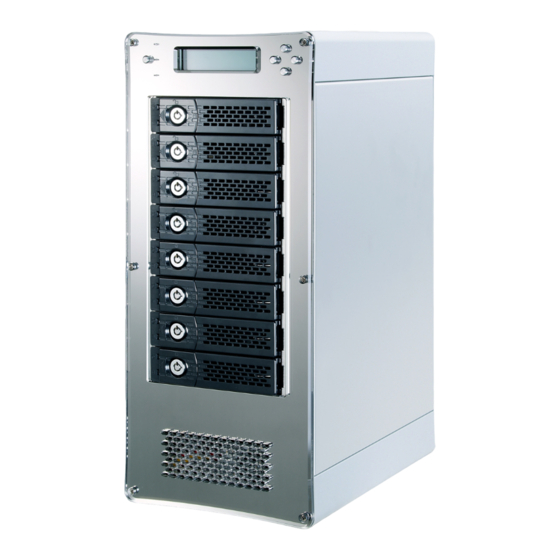
Product description Panel layout 1. Power LED 2. Mute button Reset for buzzer beeping 3. Status LED Normal green; failure red (HDD failure, fan stops, temp. over 55 , or power supply failure) 4. Access LED HDD no access – no light; HDD accessing – flashing green ... - Page 4 5. LCD (liquid crystal display) 6. ESC (Escape) (control panel button) (Up) (control panel button) 8. ENT (Enter) (control panel button) (Down) (control panel button) 10. HDD power LED white - power on indicator 11. HDD status LED flashing blue – busy (HDD accessing) indicator 12.
-
Page 5: Table Of Contents
Table of contents Chapter 1 RAID Introduction 1.1 Features……………………………………………………………………………………………………… P1 1.2 Terminology………………………………………………………………………………………………… P2 1.3 RAID levels………………………………………………………………………………………………… 1.4 Volume relationship diagram……………………………………………………………………… P4 1.5 iSCSI concepts…………………………………………………………………………………………… P5 1.6 Deployment……………………………………………………………………………………………… Chapter 2 Getting started 2.1 Before starting…………………………………………………………………………………………… P9 2.2 Management methods………………………………………………………………………… 2.2.1 Serial console……………………………………………………………………………… 2.2.2 Remote control –... - Page 6 3.7.1 Physical disk…………………………………………………………………………………… P33 3.7.2 RAID group…………………………………………………………………………………… 3.7.3 Virtual disk…………………………………………………………………………………… 3.7.4 Snapshot (optional)……………………………………………………………………… 3.7.5 Logical unit…………………………………………………………………………………… 3.7.6 Example………………………………………………………………………………………… 3.8 Enclosure management………………………………………………………………………… 3.8.1 SES configuration………………………………………………………………………… 3.8.2 Hardware monitor……………………………………………………………………… 3.8.3 Hard drive S.M.A.R.T. support………………………………………………… 3.8.4 UPS……………………………………………………………………………………………… 3.9 System maintenance…………………………………………………………………………… 3.9.1 System information…………………………………………………………………… 3.9.2 Upgrade…………………………………………………………………………………………...
- Page 7 Appendix A. Compatibility list……………………………………………………………………………………… B. Microsoft iSCSI initiator…………………………………………………………………………… P98 ...
-
Page 8: Chapter 1 Raid Introduction
• HDD S.M.A.R.T. enabled for SATA drives. • Global/dedicated cache configurable by volume. With proper configuration, Netstor product can provide non-stop service with a high degree of fault tolerance by using RAID technology and advanced array management features. Should you have any question, please feel free to contact your local sales representative or directly send email to fae@netstor.com.tw... -
Page 9: Terminology
1.2 Terminology Knowing the following terms helps you with the understanding of the using of the iSCSI enclosures. Part 1: Common ... - Page 10 Part 2: iSCSI ...
-
Page 11: Raid Levels
1.3 RAID levels 1.4 Volume relationship diagram The below graphic is the volume structure which Netstor has designed. It describes the relationship of RAID components. One RG (RAID group) consists of a set of VDs (Virtual Disk) and owns one RAID level attribute. Each RG can be divided into several VDs. -
Page 12: Iscsi Concepts
Figure 1.4.1 1.5 iSCSI concepts iSCSI (Internet SCSI) is a protocol which encapsulates SCSI (Small Computer System Interface) commands and data in TCP/IP packets for linking storage devices with servers over common IP infrastructures. iSCSI provides high performance SANs over standard IP networks like LAN, WAN or the Internet. IP SANs are true SANs (Storage Area Networks) which allow several servers to attach to an infinite number of storage volumes by using iSCSI over TCP/IP networks. - Page 13 Hardware iSCSI HBA(s) provide its own initiator tool. Please refer to the vendors’ HBA user manual. Microsoft, Linux, Solaris and Mac provide iSCSI initiator driver. Please contact Netstor for the latest certification list. Below are the available links: 1. Link to download the Microsoft iSCSI software initiator: http://www.microsoft.com/downloads/details.aspx?FamilyID=12cb3c1a-15d...
-
Page 14: Deployment
A for iSCSI initiator certification list. If user needs the latest Linux iSCSI initiator, please visit Open-iSCSI project for most update information. Linux-iSCSI (sfnet) and Open-iSCSI projects merged in April 11, 2005. Open-iSCSI website: http://www.open-iscsi.org/ Open-iSCSI README: http://www.open-iscsi.org/docs/README Features: http://www.open-iscsi.org/cgi-bin/wiki.pl/Roadmap Support Kernels: http://www.open-iscsi.org/cgi-bin/wiki.pl/Supported_Kernels Google groups:... - Page 15 1. Setup the hardware connection before power on servers. Connect console cable to console port, Ethernet cable to management port, and GbE cables to GbE (iSCSI data) ports in advance. 2. If an iSNS server is installed, then the iSNS server is served as dual controller system.
-
Page 16: Chapter 2 Getting Started
2.2.1 Serial console Use console cable (NULL modem cable) to connect from console port of Netstor iSCSI enclosure to RS 232 port of management PC. Please refer to figure 1.6.1. The console settings are on the following: Baud rate: 115200, 8 data bit, no parity, 1 stop bit, and no flow control. -
Page 17: Remote Control - Secure Shell
Login name: admin Default password: 1234 Tips: Netstor iSCSI storage only support SSH for remote control. For using SSH, the IP address and password are required for. 2.2.3 LCM There are four buttons to control Netstor LCM (LCD Control Module), including: (up), (down), ESC (Escape), and ENT (Enter). - Page 18 LCM operation description: ...
- Page 19 The following is LCM menu hierarchy. Caution: Before power off, it is better to execute “Shutdown” to flush the data from cache to physical disks. ...
-
Page 20: System Buzzer
2.2.3.2 LED For Netstor iSCSI enclosure, there are two LEDs in front of the enclosure, and two LEDs on the HDD tray. The two LEDs in front of the enclosure are Status LED and Access LED. For Status LED, when LED shows green, it means normal;... - Page 21 Take an example on LCM: 192.168.0.154 IP Storage Figure 2.2.1.1 http://192.168.0.154 Click any function at the first time; it will pop up a dialog to authenticate current user. Login name: admin Default password: 1234 Or login with read-only account which only allows to read the configuration but cannot change setting.
-
Page 22: Chapter 3 Web Gui Guideline
Chapter 3 Web GUI guideline 3.1 Web GUI hierarchy The below table is the hierarchy of web GUI. ... -
Page 23: Login
3.2 Login Netstor iSCSI storage supports graphic user interface (GUI) to operate the system. Be sure to connect the LAN cable. The default IP setting is DHCP; open the browser and enter: http://192.168.xx.xx (Please check the DHCP address first on LCM.) Then the login screen will show up as follows. - Page 24 You can choose the functions which lists on the left side of window to setup configuration. Figure 3.2.1 There are six indicators at the top-right corner. Figure 3.2.2 ...
- Page 25 Indicator description: Tips: If the status indicators in Internet Explorer (IE) are displayed in gray, but not in blinking red, please enable “Internet Options” “Advanced” “Play animations in webpages” options in IE. The default value is enabled, but some applications will disable it.
-
Page 26: Quick Installation
3.3 Quick installation It is easy to use “Quick install” to create a volume. It uses whole physical disks to create a RG; the system will calculate maximum spaces on RAID levels 0 / 1 / 3 / 5 / 6 / 0+1. “Quick install” will occupy all residual RG space for one VD, and it has no space for snapshot and spare. - Page 27 (free status). The result is using smarter policy designed by Netstor. It gives user: 1. Biggest capacity of RAID level for user to choose and, 2. The fewest disk number for RAID level / volume size. E.g., user chooses RAID 5 and the system has 12*200G + 4*80G HDDs inserted.
-
Page 28: System Configuration
Step 3: Decide VD size. User can enter a number less or equal to the default number. Then click “Next”. Figure 3.4.3 Step 4: Confirm page. Click “Confirm” if all setups are correct. Then a VD will be created. Step 5: Done. You can start to use the system now. Figure 3.4.4 (Figure 3.4.4: A virtual disk of RAID 0 is created and is named by system itself.) -
Page 29: System Setting
Figure 3.5.1 3.5.1 System setting “System setting” can setup system name and date. Default “System name” is composed of model name and serial number of this system. Figure 3.5.1.1 Check “Change date and time” to set up the current date, time, and time zone before using or synchronize time from NTP (Network Time Protocol) server. -
Page 30: Ip Address
3.5.2 IP address “IP address” is for changing IP address for remote administration usage. There are two options, DHCP (Get IP address from DHCP server), BOOTP (Get IP address from BOOTP server) and static IP. The default setting is DHCP. User can change the HTTP, HTTPS, and SSH port number when the default port number is not allowed on host. -
Page 31: Mail Setting
2. Login lock: Disabled or Enabled. When the login lock is enabled, the system allows only one user to login or modify system settings. Figure 3.5.3.1 Check “Change admin password” or “Change user password” to change admin or user password. The maximum length of password is 12 characters. 3.5.4 Mail setting “Mail setting”... -
Page 32: Notification Setting
Figure 3.5.4.1 3.5.5 Notification setting “Notification setting” can set up SNMP trap for alerting via SNMP, pop-up message via Windows messenger (not MSN), alert via syslog protocol, and event log filter for web UI and LCM notifications. Figure 3.5.5.1 ... -
Page 33: Iscsi Configuration
“SNMP” allows up to 3 SNMP trap addresses. Default community setting is “public”. User can choose the event log levels and default setting enables ERROR and WARNING event log in SNMP. There are many SNMP tools. The following web sites are for your reference: SNMPc: http://www.snmpc.com/ Net-SNMP: http://net-snmp.sourceforge.net/ If necessary, click “Download”... -
Page 34: Entity Property
3.6.1 Entity property When you want to view the entity name of the system (iSCSI enclosure), click Entity property in iSCSI configuration on the left side of the web GUI. Then the entity name of the system will appear at the center of the screen. Please note that the entity name of the system (NR760A-IP2 / NR340A-IP2 / NR330A-IP4) can not be changed. - Page 35 Figure 3.6.2.2 (NR330A-IP4) (Figure 3.5.2.2: There are 4 iSCSI data ports. 4 data ports are set with static IP.) · IP settings: User can change IP address by checking the gray button of LAN port, click “IP settings for iSCSI ports”. There are 2 selections, DHCP (Get IP address from DHCP server) or static IP.
- Page 36 Multi-homed / Trunking / LACP: The following is the description of multi-homed / trunking / LACP functions. 1. Multi-homed: Default mode. Each of iSCSI data port is connected by itself and is not link aggregation and trunking. This function is also for Multipath functions.
-
Page 37: Node
Figure 3.6.2.6 (NR330A-IP4) Figure 3.6.2.7 (NR330A-IP4) For example, LAN1 and LAN2 are set as Trunking mode. LAN3 and LAN4 are set as LACP mode. To remove Trunking / LACP setting, checking the gray button of LAN port, click “Delete link aggregation”. Then it will pop up a message to confirm. -
Page 38: Session
a key to be used for encrypting the username and password. CHAP enables the username and password to transmit in an encrypted form for protection. To use CHAP authentication, please follow the procedures. 1. Click “Authenticate”. 2. Select “CHAP”. Figure 3.6.3.2 3. -
Page 39: Chap Account
Figure 3.6.4.1 Check the gray button of session number, click “List connection”. It can list all connection(s) of the session. Figure 3.6.4.2 3.6.5 CHAP account “CHAP account” can manage a CHAP account for authentication. NR760A-IP2 / NR340A-IP2 / NR330A-IP4 can create a CHAP account. To setup CHAP account, please follow the procedures. -
Page 40: Physical Disk
Figure 3.7.1 3.7.1 Physical disk “Physical disk” can view the status of hard drives in the system. The followings are operational steps: 1. Check the gray button next to the number of slot, it will show the functions which can be executed. 2. - Page 41 Step 3: Done. View “Physical disk” page. Figure 3.7.1.3 (Figure 3.7.1.3: Physical disks in slot 1,2,3 are created for a RG named “RG-R5”. Slot 4 is set as dedicated spare disk of the RG named “RG-R5”. The others are free disks.) Step 4: The unit of size can be changed from (GB) to (MB).
- Page 42 Status The status of hard drive: “Online” the hard drive is online. “Rebuilding” the hard drive is being rebuilt. “Transition” the hard drive is being migrated or is replaced by another disk when rebuilding occurs. “Scrubbing” the hard drive is being scrubbed. Health The health of hard drive: “Good”...
-
Page 43: Raid Group
PD operation description: Set Free disk Make the selected hard drive be free for use. Set Global Set the selected hard drive to global spare of all RGs. spare Set a hard drive to dedicated spare of the selected RG. Dedicated spares Disk Scrub... - Page 44 Figure 3.7.2.1 Step 2: Confirm page. Click “Confirm” if all setups are correct. Figure 3.7.2.2 (Figure 3.7.2.2: There is a RAID 0 with 4 physical disks, named “RG-R0”. The second RAID group is a RAID 5 with 3 physical disks, named “RG-R5”.) Step 3: Done.
- Page 45 RG column description: RAID group number. The button next to the No. includes the functions which can be executed. Name RAID group name. Total (GB) Total capacity of this RAID group. The unit can be displayed in (MB) GB or MB. Free (GB) Free capacity of this RAID group.
- Page 46 Activate the RAID group after disk roaming; it can be executed when Activate RG status is offline. This is for online disk roaming purpose. Deactivate Deactivate the RAID group before disk roaming; it can be executed when RG status is online. This is for online disk roaming purpose.
-
Page 47: Virtual Disk
3.7.3 Virtual disk “Virtual disk” can view the status of each Virtual disk, create, and modify virtual disks. The following is an example to create a VD. Step 1: Click “Create”, enter “Name”, select RAID group from “RG name”, enter required “Capacity (GB)/(MB)”, change “Stripe height (KB)”,... - Page 48 Figure 3.7.3.2 (Figure 3.7.3.2: Create a VD named “VD-01”, from “RG-R0”. The second VD is named “VD-02”, it’s initializing.) Step 3: Done. View “Virtual disk” page. VD column description: Virtual disk number. The button includes the functions which can be executed. Name Virtual disk name.
- Page 49 Bg rate Background task priority: “4 / 3 / 2 / 1 / 0” Default value is 4. The higher number the background priority of a VD is, the more background I/O will be scheduled to execute. Status The status of virtual disk: “Online”...
- Page 50 #LUN Number of LUN(s) that virtual disk is attached to. Snapshot The virtual disk size that is used for snapshot. The number means (GB) (MB) “Used snapshot space” / “Total snapshot space”. The unit can be displayed in GB or MB. #Snapshot Number of snapshot(s) that have been taken.
- Page 51 Set property Change the VD name, right, priority, bg rate and read ahead. Right: “WT” Write Through. “WB” Write Back. (Default) “RO” Read Only. Priority: “HI” HIgh priority. (Default) “MD” MiDdle priority. “LO” priority. Bg rate: “4 / 3 / 2 / 1 / 0” Default value is 4.
-
Page 52: Snapshot (Optional)
Set snapshot Set snapshot space for taking snapshot. Please refer to next space chapter for more detail. Cleanup Clean all snapshots of a VD and release the snapshot space. snapshot Take Take a snapshot on the virtual disk. snapshot Auto Set auto snapshot on the virtual disk. - Page 53 Step 3: Take a snapshot. In “/ Volume configuration / Snapshot”, click “Take snapshot”. It will link to next page. Enter a snapshot name. Figure 3.7.4.3 Step 4: Expose the snapshot VD. Check the gray button next to the Snapshot VD number;...
- Page 54 Snapshot column description: The number of this snapshot VD. The button next to the snapshot VD No. includes the functions which can be executed. Name Snapshot VD name. Used (GB) The amount of snapshot space that has been used. The unit can be (MB) displayed in GB or MB.
-
Page 55: Logical Unit
Figure 3.7.5.2 (NR760A-IP2 / NR340A-IP2 / NR330A-IP4) (Figure 3.7.5.2: VD-01 is attached to LUN 0 and every host can access. VD-02 is attached to LUN 1 and only the initiator node which is named “iqn.2001-10.com.microsoft:netstor” can access.) LUN operation description: Attach Attach a logical unit number to a virtual disk. -
Page 56: Example
Wildcard “*” and “?” are allowed in this field. “*” can replace any word. “?” can replace only one character. For example: “iqn.host?” “iqn.host1” and “iqn.host2” are accepted. “iqn.host*” “iqn.host1” and “iqn.host12345” are accepted. This field can not accept comma, so “iqn.host1, iqn.host2” stands a long string, not 2 iqns. - Page 57 Figure 3.7.6.2 (Figure 3.6.6.2: Creating a RAID 5 with 3 physical disks, named “RG-R5”.) Step 2: Create VD (Virtual Disk). To create a data user volume, please follow the procedures. Figure 3.7.6.3 1. Select “/ Volume configuration / Virtual disk”. 2.
- Page 58 Step 3: Attach a LUN to a VD. There are 2 methods to attach a LUN to a VD. 1. “/ Volume configuration / Virtual disk”, check the gray button next to the VD number; click “Attach LUN”. 2. In “/ Volume configuration / Logical unit”, click “Attach”. The procedures are as follows: Figure 3.7.6.5 1.
- Page 59 Step 4: Set a global spare disk. To set a global spare disk, please follow the procedures. 1. Select “/ Volume configuration / Physical disk”. 2. Check the gray button next to the PD slot; click “Set global space”. 3. “Global spare” status is shown in “Usage” column. Figure 3.7.6.7 (Figure 3.6.6.7: Slot 4 is set as a global spare disk.) Step 5: Done.
-
Page 60: Enclosure Management
1. Select “/ Volume configuration / Virtual disk”. 2. Check the gray button next to the VD number; click “Delete”. There will pop up a confirmation page, click “OK”. 3. Done. Then, the VD is deleted. Tips: When deleting VD directly, the attached LUN(s) of to this VD will be detached together. -
Page 61: Ses Configuration
sensors, and LED status. Due to the different hardware characteristics among these sensors, they have different polling intervals. Below are the details of the polling time intervals: 1. Temperature sensors: 1 minute. 2. Voltage sensors: 1 minute. 3. Hard disk sensors: 10 minutes. 4. -
Page 62: Hardware Monitor
3.8.2 Hardware monitor “Hardware monitor” can view the information of current voltages and temperatures. Figure 3.8.2.1 If “Auto shutdown” is checked, the system will shutdown automatically when voltage or temperature is out of the normal range. For better data protection, please check “Auto Shutdown”. -
Page 63: Hard Drive S.m.a.r.t. Support
3. If the high temperature situation doesn’t last for 3 minutes, system will not trigger auto shutdown. 3.8.3 Hard drive S.M.A.R.T. support S.M.A.R.T. (Self-Monitoring Analysis and Reporting Technology) is a diagnostic tool for hard drives to deliver warning of drive failures in advance. S.M.A.R.T. provides users chances to take actions before possible drive failure. -
Page 64: Ups
3.8.4 UPS “UPS” can set up UPS (Uninterruptible Power Supply). Figure 3.8.4.1 (Figure 3.8.4.1: Without UPS.) Currently, the system supports the UPS features of APC (American Power Conversion Corp.) smart-UPS series only. Please review the details from the website: http://www.apc.com/ . Connection with other vendors of UPS can work well, but they have no such communication features with the system. -
Page 65: System Maintenance
If power failure occurs and system power can not recover after the Shutdown time setting, the system will shutdown. Setting delay to “0” will delay (s) disable the function. Select ON, when power is gone, UPS will shutdown by itself after the Shutdown system shutdown successfully. -
Page 66: System Information
Figure 3.9.1 3.9.1 System information “System information” can display system information, including firmware version, CPU type, installed system memory, serial number and backplane ID Figure 3.9.1.1 (NR760A-IP2 / NR340A-IP2) Figure 3.9.1.2 (NR330A-IP4) 3.9.2 Upgrade “Upgrade” can upgrade controller firmware. Before upgrade, it’s better to use “Export”... -
Page 67: Reset To Factory Default
Figure 3.9.2.1 Please prepare new controller firmware file named “xxxx.bin” in local hard drive, then click “Browse” to select the file. Click “Confirm”, it will pop up a warning message, click “OK” to start to upgrade firmware. Figure 3.9.2.2 When upgrading, there is a progress bar running. After finished upgrading, the system must reboot manually to make the new firmware took effect. -
Page 68: Import And Export
3.9.4 Import and export “Import and export” allows user to save system configuration values: export, and apply all configuration: import. For the volume configuration setting, the values are available in export and not available in import which can avoid confliction / date-deleting between two controllers which mean if one system already has valuable volumes in the disks and user may forget and overwrite it. -
Page 69: Reboot And Shutdown
Figure 3.9.5.1 The event log is displayed in reverse order which means the latest event log is on the first / top page. The event logs are actually saved in the first four hard drives; each hard drive has one copy of event log. For one system, there are four copies of event logs to make sure users can check event log any time when there are failed disks. -
Page 70: Chapter 4 Advanced Operations
But rebuilding in the same failed disk may impact customer data if the status of disk is unstable. Netstor suggests all customers not to rebuild in the failed disk for better data protection. - Page 71 Tips: “Set dedicated spare” is not available if there is no RG or only RG of RAID 0, JBOD, because user can not set dedicated spare disk to RAID 0 and JBOD. Sometimes, rebuild is called recover; they are the same meaning. The following table is the relationship between RAID levels and rebuild.
-
Page 72: Rg Migration And Moving
RAID 60 Striping over the member of RAID 6 volumes. RAID 60 allows four hard drive failures or unplugging, every two in different arrays. JBOD abbreviation “Just Bunch Disks”. data protection. RG fails if any hard drive failures or unplugs. 4.2 RG migration and moving To do migration, the total size of RG must be larger or equal to the original RG. - Page 73 10. Delete a snapshot. 11. Expose a snapshot. 12. Rollback to a snapshot. Caution: RG migration or moving cannot be executed during rebuilding or VD extension. Tips: “Migrate” function will migrate the member disks of RG to the same physical disks but it should increase the number of disks or it should be different RAID level.
-
Page 74: Vd Extension
6. Migration starts and it can be seen from the “status” of a RG with “Migrating”. In “/ Volume configuration / Virtual disk”, it displays a “Migrating” in “Status” and complete percentage of migration in “R%”. Figure 4.2.3 (Figure 4.2.3: A RAID 0 with 3 physical disks migrates to RAID 5 with 4 physical disks.) Figure 4.2.4 4.3 VD extension... -
Page 75: Qsnap (Optional)
Caution: VD Extension cannot be executed during rebuilding or migration. 4.4 QSnap (optional) Snapshot-on-the-box (QSnap) captures the instant state of data in the target volume in a logical sense. The underlying logic is Copy-on-Write -- moving out the data which would be written to certain location where a write action occurs since the time of data capture. - Page 76 size, and then click “OK”. It will go back to the VD page and the size will show in snapshot column. It may not be the same as the number entered because some size is reserved for snapshot internal usage. There will be 2 numbers in “Snapshot”...
-
Page 77: Auto Snapshot
1. There are two methods to clean all snapshots. In “/ Volume configuration / Virtual disk”, check the gray button next to the VD number; click “Cleanup snapshot”. Or in “/ Volume configuration / Snapshot”, click “Cleanup”. 2. “Cleanup” will delete all snapshots of the VD and release snapshot space. 4.4.2 Auto snapshot The snapshot copies can be taken manually or by schedule such as hourly or daily. -
Page 78: Rollback
4.4.4 QSnap constraint Netstor snapshot function applies Copy-on-Write technique on UDV/VD and provides a quick and efficient backup methodology. When taking a snapshot, it does not copy any data at first time until a request of data modification comes in. - Page 79 Figure 4.4.4.1 On Linux and UNIX platform, a command named sync can be used to make the operating system flush data from write caching into disk. For Windows platform, Microsoft also provides a tool – sync, which can do exactly the same thing as the sync command in Linux/UNIX.
- Page 80 What if the snapshot space is over? Before using snapshot, a snapshot space is needed from RG capacity. After a period of working snapshot, what if the snapshot size over the snapshot space of user defined? There are two different situations: 1.
-
Page 81: Disk Roaming
4.5 Disk roaming Physical disks can be re-sequenced in the same system or move all physical disks in the same RAID group from system-1 to system-2. This is called disk roaming. System can execute disk roaming online. Please follow the procedures. 1. - Page 82 Start VD clone 1. Create a RAID group (RG) in advance. Figure 4.6.1 2. Create two virtual disks (VD) “SourceVD_R5” and “TargetVD_R6”. The raid type of backup target needs to be set as “BACKUP”. Figure 4.6.2 3. Here are the objects, a Source VD and a Target VD. Before starting clone process, it needs to deploy the VD Clone rule first.
- Page 83 Figure 4.6.4 Snapshot space: Figure 4.6.5 This setting is the ratio of source VD and snapshot space. The default ratio is 2 to 1. It means when the clone process is starting, the system will automatically use the free RG space to create a snapshot space which capacity is double the source Threshold: (The setting will be effective after enabling schedule clone) Figure 4.6.6 The threshold setting will monitor the usage amount of snapshot space.
- Page 84 The default snapshot space allocated by the subsystem is two times the size of source virtual disk. That is the best value of Netstor’s suggestion. If user sets snapshot space by manually and lower than the default value, user should take the risk if the snapshot space is not enough and VD clone job will fail.
- Page 85 6. Select the target VD. Then click “Confirm”. Figure 4.6.9 7. Now, the clone target “TargetVD_R6” has been set. Figure 4.6.10 8. Click “Start clone”, the clone process will start. Figure 4.6.11 9. The default setting will create a snapshot space automatically which the capacity is double size of the VD space.
- Page 86 Figure 4.6.12 10. After initiating the snapshot space, it will start cloning. Figure 4.6.13 11. Click “Schedule clone” to set up the clone by schedule. Figure 4.6.14 12. There are “Set Clone schedule” and “Clear Clone schedule” in this page. Please remember that “Threshold”...
- Page 87 Figure 4.6.15 Run out of snapshot space while VD clone While the clone is processing, the increment data of this VD is over the snapshot space. The clone will complete, but the clone snapshot will fail. Next time, when trying to start clone, it will get a warning message “This is not enough of snapshot space for the operation”.
- Page 88 Figure 4.6.16 ...
-
Page 89: Mpio And Mc/S
4.7 MPIO and MC/S These features come from iSCSi initiator. They can be setup from iSCSI initiator to establish redundant paths for sending I/O from the initiator to the target. 1. MPIO: In Microsoft Windows server base system, Microsoft MPIO driver allows initiators to login multiple sessions to the same target and aggregate the duplicate devices into a single device. - Page 90 Figure 4.7.2 Difference: MC/S is implemented on iSCSI level, while MPIO is implemented on the higher level. Hence, all MPIO infrastructures are shared among all SCSI transports, including Fiber Channel, SAS, etc. MPIO is the most common usage across all OS vendors.
-
Page 91: Trunking And Lacp
A network switch negotiates an automatic bundle by sending LACP packets to the peer. Theoretically, LACP port can be defined as active or passive. Netstor controller implements it as active mode which means that LACP port sends LACP protocol packets automatically. - Page 92 2. Trunking (Non-protocol): Defines the usage of multiple iSCSI data ports in parallel to increase the link speed beyond the limits of any single port. The usage occasion of Trunking: A. This is a simple SAN environment. There is only one switch to connect the server and storage.
-
Page 93: Chapter 5 Troubleshooting
Chapter 5 Troubleshooting 5.1 System buzzer The system buzzer features are listed below: 1. The system buzzer alarms 1 second when system boots up successfully. 2. The system buzzer alarms continuously when there is error occurred. The alarm will be stopped after error resolved or be muted. 3. - Page 94 ERROR SATA PRD mem fail Failed to init SATA PRD memory manager ERROR SATA revision id fail Failed to get SATA revision id ERROR SATA set reg fail Failed to set SATA register ERROR SATA init fail Core failed to initialize the SATA adapter ERROR SATA diag fail SATA Adapter diagnostics failed...
- Page 95 RMS events Level Type Description INFO Console Login <username> login from <IP or serial console> via Console INFO Console Logout <username> logout from <IP or serial console> via Console INFO Web Login <username> login from <IP> via Web UI INFO Web Logout <username>...
- Page 96 ERROR VD move failed Failed to complete move of VD <name>. INFO RG activated RG <name> has been manually activated. INFO RG deactivated RG <name> has been manually deactivated. INFO VD rewrite started Rewrite at LBA <address> of VD <name> starts. INFO VD rewrite finished Rewrite at LBA <address>...
- Page 97 Snapshot events Level Type Description WARNING Snap mem Failed to allocate snapshot memory for VD <name>. WARNING Snap space Failed to allocate snapshot space for VD <name>. overflow The snapshot space threshold of VD <name> has been WARNING Snap threshold reached.
- Page 98 WARNING PD upgrade failed JBOD <name> PD [<string>] upgrade firmware failed. INFO PD freed JBOD <name> PD <slot> has been freed from RG <name>. INFO PD inserted JBOD <name> disk <slot> is inserted into system. Warning PD removed JBOD <name> disk <slot> is removed from system. ERROR HDD read error JBOD <name>...
- Page 99 INFO System reboot System reboot. INFO System console System shutdown from <string> via Console UI shutdown INFO System web System shutdown from <string> via Web UI shutdown System button INFO System shutdown via power button shutdown INFO System LCM System shutdown via LCM shutdown INFO System console...
-
Page 100: How To Get Support
5.3 How to get support If there are any problems to use NR760A-IP2 / NR340A-IP2 / NR330A-IP4, please fill in a Netstor Support Form on the following, and then send it to fae@netstor.com.tw , the support team will answer the questions as soon as possible. - Page 101 Netstor Support Form version: 1.1 Customer information Customer name Contact email Target information Model name (*) Hardware version MB (Main board): DB (Daughter board): Serial number (1) Firmware version (*)(2) Backplane / Chassis model Backplane version Target configuration (*) RAID...
- Page 102 Connect diagram Attached file name: Problem description (*) Reproduce step (*) Screenshot Attached file name: Netstor description ...
- Page 103 Fields marked as (*) are MUST. At least, these informations are MUST to have. Fields marked as (1)(2)(3)(4), you can get them on the following descriptions. (1) In / Maintenance / Info / Controller serial no. or In / Maintenance / System information / Controller serial no. (2) In / Maintenance / Info / System information or In / Maintenance / System information / System information (3) In / Maintenance / Config import &...
-
Page 104: Sata Hard Drive
GbE iSCSI HBA card Vendor Model Bus Type Port BIOS Comment NC380T PCI-E Gigabit 1.9.6 iSCSI offload NC7170 PCI-X Gigabit NC360T PCI-E Gigabit NetXtreme PCI-X Gigabit 1000 PWLA8492MT Intel PCI-X Gigabiti QLogic QLA4052 PCI-X Gigabit 1.15 3.0.1.53 iSCSI offload QLogic QLE4062C PCI-E Gigabit... - Page 105 7200 3Gb/s SN02 Please contact fae@netstor.com.tw to get the newest compatibility list. B. Microsoft iSCSI initiator Here is the step by step to setup Microsoft iSCSI Initiator. Please visit Microsoft website for latest iSCSI initiator. This example is based on Microsoft Windows Server 2008 R2.
- Page 106 3. Click “Done”. Figure B.2 Figure B.3 ...
- Page 107 4. It can connect to an iSCSI disk now. MPIO 5. If running MPIO, please continue. 6. Click “Discovery” tab to connect the second path. 7. Click “Discover Portal”. Input IP address or DNS name of the target. Figure B.4 Figure B.5 ...
- Page 108 8. Click “OK”. Figure B.6 Figure B.7 9. Click “Targets” tab, select the second path, and then click “Connect”. 10. Enable “Enable multi-path” checkbox. Then click “OK”. 11. Done, it can connect to an iSCSI disk with MPIO. MC/S 12. If running MC/S, please continue. 13.
- Page 109 Figure B.8 Figure B.9 ...
- Page 110 15. Click “Add…”. 16. Click “Advanced…”. Figure B.10 Figure B.11 17. Select Initiator IP and Target portal IP, and then click “OK”. 18. Click “Connect”. 19. Click “OK”. ...
- Page 111 Figure B.12 Figure B.13 20. Done. ...
- Page 112 Disconnect 21. Select the target name, click “Disconnect”, and then click “Yes”. Figure B.14 22. Done, the iSCSI device disconnect successfully. System information NR760A-IP2 / NR340A-IP2 / NR330A-IP4 SW version 1.0.XX ...
Need help?
Do you have a question about the NR760A-IP and is the answer not in the manual?
Questions and answers