
Related Manuals for AXIOMTEK GOT3187W-881-PCT


Summary of Contents for AXIOMTEK GOT3187W-881-PCT
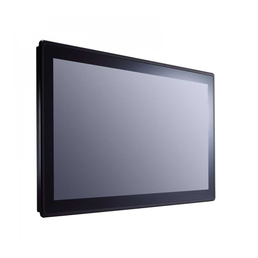
- Page 1 GOT3187W-881-PCT All-in-One 18.5” WXGA TFT Fanless Multi-Touch PANEL PC User’s Manual...
-
Page 2: Disclaimers
Axiomtek does not make any commitment to update the information in this manual. Axiomtek reserves the right to change or revise this document and/or product at any time without notice. No part of this document may be reproduced, stored in a retrieval system, or transmitted, in any form or by any means, electronic, mechanical, photocopying, recording, or otherwise, without the prior written permission of Axiomtek Co., Ltd. -
Page 3: Safety Precautions
Most electronic components are sensitive to static electrical charge. Disconnect the power cords from the GOT3187W-881-PCT Series before making any installation. Be sure both the system and the external devices are turned OFF. Sudden surge of power could ruin sensitive components. Make sure the GOT3187W-881-PCT Series is properly grounded. -
Page 4: Table Of Contents
Table of Contents Disclaimers ..................... ii Safety Precautions ..................iii Chapter 1 Introduction ..........1 General Description ................1 Specifications ..................2 Dimensions and Outlines ..............4 I/O Outlets .................... 5 Packing List ..................6 Chapter 2 Hardware and Installation ...... 7 CFast card Installation ................ - Page 5 Main Menu ..................28 Advanced Menu ................. 29 Chipset Menu ..................39 Boot Menu ..................44 Security Menu ..................45 Save & Exit Menu ................46 Chapter 4 Drivers Installation ........ 49 Driver CD/DVD content ..............49 Touch Screen ..................50...
- Page 6 This page is intentionally left blank.
-
Page 7: Chapter 1 Introduction
This platform is a power-efficient solution. Reliable and Stable Design The GOT3187W-881-PCT is a fanless cooling system, which makes it suitable for vibration environments, such as the industrial machinery markets. For high capacity storage requirement, GOT3187W-881-PCT can work under 1.2G (5 ~ 500Hz, random for CFast card) in operation mode with a patent of anti-vibration design. -
Page 8: Specifications
The hardness of touch glass surface is up to 7h and is better for anti-scratch purpose. WLAN Antenna Supported (optional) GOT3187W-881-PCT has dual PCIe Mini Card slots for optional add-ons such as mSATA storage、wireless LAN card for 802.11 b/g/n connections or 3G/GPRS applications, and more. - Page 9 GOT3187W-881-PCT User’s Manual System Specification 18.5” WXVGA(1366x768) LCD with LED backlight & 300nits brightness Projected Capacitive Multi Touch Fanless Heat Dispensing Design IP65 front bezel Disk drive housing: 1x 2.5” SATA drive Net Weight ...
-
Page 10: Dimensions And Outlines
GOT3187W-881-PCT User’s Manual Dimensions and Outlines The following diagrams show the dimensions and outlines of GOT3187W-881-PCT Outline Dimension: 460x285x89.5(mm) Cut out: 448.74x237.74mm Introduction... -
Page 11: I/O Outlets
GOT3187W-881-PCT User’s Manual I/O Outlets Please refer to the following illustration for I/O locations of the GOT3187W-881-PCT. Function Function POWER SWITCH (ATX) 2 x USB 2.0 Power Input connector 2 x USB 3.0 Audio Line-out CFast card slot Audio MIC-in... -
Page 12: Packing List
Panel mount kit x 12 Screws for HDD x 4 SATA data cable x 1 SATA power cable x 1 If you can not find the package or any items are missing, please contact Axiomtek distributors immediately. Introduction... -
Page 13: Hardware And Installation
GOT3187W-881-PCT User’s Manual Chapter 2 Hardware and Installation The GOT3187W-881-PCT provides rich I/O ports and flexible expansions for you to meet different demand, for example CF card. The chapter will show you how to install the hardware. It includes: ... -
Page 14: Cfast Card Installation
GOT3187W-881-PCT User’s Manual CFast card Installation The GOT3187W-881-PCT provides one CFast card slot for users to install CFast card. Please refer to the following instructions for installation: Step 1 Open the cover, unscrew 2 screws on the chassis. Step 2 Stick the mylar on the CFast card bottom side. -
Page 15: Open
GOT3187W-881-PCT User’s Manual Open back cover This section tells users how to open back cover. Please follow the steps below. Step 1 Unscrew 6 screws on the back cover. Please refer the drawing below. Step 2 Remove the back cover. -
Page 16: Jumper And Com Port Connector
GOT3187W-881-PCT User’s Manual Jumper and COM port Connector SBC87881 Top Side Hardware and Installation... -
Page 17: Cmos Clear Jumper (Sjp2 On Sbc87881)
GOT3187W-881-PCT User’s Manual Jumper is a small component consisting of jumper clip and jumper pins. Install jumper clip on 2 jumper pins to close. And remove jumper clip from 2 jumper pins to open. The following illustration shows how to set up jumper. -
Page 18: Dc Power In Connector (Scn1)
GOT3187W-881-PCT User’s Manual 2.3.2 DC Power In Connector (SCN1) The system supports a DC 19V power-din connector for system power input. Signal DC 19V DC 19V 2.3.3 HDMI Connector The HDMI (High-Definition Multimedia Interface) is a compact digital interface which is capable of transmitting high-definition video and high-resolution audio over a single cable. -
Page 19: Com Serial Port Connector
GOT3187W-881-PCT User’s Manual 2.3.4 COM Serial Port Connector The system has six serial ports. COM1/2 are RS-232/422/485 ports. Please refer to Chapter 3 for the detail of BIOS setting. RS-232 RS-422 RS-485 Data- DCD, Data Carrier Detect Data+ RXD, Receive Data... -
Page 20: Serial Ata Connectors
Signal SATA_TX+ SATA_TX- SATA_RX- SATA_RX+ 2.3.7 SIM Card Slots (SCN19) GOT3187W-881-PCT includes one SIM slots on the bottom side of the system for inserting SIM Card. It is mainly used in 3G wireless network application. Signal Hardware and Installation... -
Page 21: Cfast™ Socket
GOT3187W-881-PCT User’s Manual 2.3.8 CFast™ Socket The system is equipped with a CFast™ socket on the top size of rear housing to support a CFast™ card which is based on the Serial ATA bus. The socket is specially designed to avoid incorrect installation of the CFast™... -
Page 22: Half-Size Express Mini Card Slot (Scn13)
GOT3187W-881-PCT User’s Manual 2.3.9 Half-Size Express Mini Card Slot (SCN13) PCI Express Mini Card connector supports a PCI Express x1 link and a USB 2.0 link. A PCI Express Mini Card can be applied to either PCI Express or USB 2.0. It complies with PCI-Express Mini Card Spec. -
Page 23: Full-Size Express Mini Card (W/ Sim Slot)/ Msata (Scn14)
GOT3187W-881-PCT User’s Manual 2.3.10 Full-Size Express Mini Card (w/ SIM Slot)/ mSATA (SCN14) You may need to adjust the BIOS setting to select mSATA or Mini card PCI-E interface. This is a PCI-Express Mini Card connector which supports PCI-Express x1 link ,SATA link , USB 2.0 link and 3G wireless network application(SCN19). -
Page 24: Mountings: Panel / Wall / Desktop / Vesa
2.4.1 VESA/Wall-Mount The GOT3187W-881-PCT provides VESA mount: 100x100 mm. Screw four screws to fix the kit in the back chassis. About the mount, users need to buy optional wall mount kit via Axiomtek and install it on the rear cover. -
Page 25: Panel-Mount Kit Assembly
GOT3187W-881-PCT User’s Manual 2.4.2 Panel-mount Kit Assembly The GOT3187W-881-PCT is designed for panel mount application. To mount the GOT3187W-881-PCT, the standard set of mounting kit (included in the system packaging) is needed. Hardware and Installation... -
Page 26: Hdd Installation
GOT3187W-881-PCT User’s Manual HDD Installation The GOT3187W-881-PCT provides a convenient Hard Disk Drive (HDD) bracket for users to install 2.5” SATA HDD. Please follow the steps: Step 1 Refer section 2.2 to open the back cover. Step 2 Remove the HDD tray and install 2.5” HDD driver with 4 screws. - Page 27 GOT3187W-881-PCT User’s Manual Step 3 Plug the cables to connectors and screw the HDD tray on the bracket. Installation completes. Hardware and Installation...
-
Page 28: Installing Cpu And Pch Thermal Pad
We have installed CPU and thermal pads already. This chapter just to let you know how to replace new thermal pad by yourself. If any further information is requested, please feel free to contact Axiomtek distributors or FAE immediately. Hardware and Installation... -
Page 29: Dram Installation
GOT3187W-881-PCT User’s Manual DRAM Installation The GOT3187W-881-PCT provides one 204-pin DDR3 SODIMM socket that supports system memory up to 8GB. Please follow steps below to install the memory modules: Step 1 Refer to section 2.2 to open the back cover. -
Page 30: Wireless Lan Card Installation
GOT3187W-881-PCT User’s Manual Wireless LAN Card Installation The GOT3187W-881-PCT provides one Mini card slot for user to install one wireless LAN card. When installing the wireless LAN card, refer to the following instructions and illustration: Step 1 Refer to section 2.2 to open the back cover and find out mini-card slot on mainboard. - Page 31 GOT3187W-881-PCT User’s Manual Step 3 Find the Antenna cable and connect it on wireless LAN card. …. Hardware and Installation...
-
Page 32: Power Adapter Installation
Please have the extended bracket when using half-size mini card. Power Adapter Installation Step 1 Please connect power adapter to GOT3187W-881-PCT at first. The connector is with special shape to prevent wrong connection. Step 2 Connect power cord to power adapter. -
Page 33: Ami Bios Setup Utility
GOT3187W-881-PCT User’s Manual Chapter 3 AMI BIOS Setup Utility The AMI BIOS provides users with a built-in setup program to modify basic system configuration. All configured parameters are stored in a battery-backed CMOS to save the setup information whenever the power is turned off. This chapter provides users with detailed description about how to set up basic system configuration through the AMI BIOS setup utility. -
Page 34: Main Menu
GOT3187W-881-PCT User’s Manual Main Menu When you first enter the setup utility, you will enter the Main setup screen. You can always return to the Main setup screen by selecting the Main tab. System Time/Date can be set up as described below. -
Page 35: Advanced Menu
GOT3187W-881-PCT User’s Manual Advanced Menu mSATA/PCIE select Use this item to select the SCN14 to mSATA or Mini-PCIE mode. Launch PXE OpROM Use this item to enable or disable the boot ROM function of the onboard LAN chip when the system boots up. - Page 36 GOT3187W-881-PCT User’s Manual ACPI Settings You can use this screen to select options for the ACPI configuration, and change the value of the selected option. A description of the selected item appears on the right side of the screen.
- Page 37 GOT3187W-881-PCT User’s Manual CPU Configuration This screen shows the CPU Configuration, and you can change the value of the selected option. Hyper-threading This item can set enable or disable for support Hyper-threading Technology. Intel Virtualization Technology Allow you to enable or disable Intel Virtualization Technology. When enabled, a VMM can utilize the additional hardware capabilities provided by Vanderpool Technology.
- Page 38 GOT3187W-881-PCT User’s Manual SATA Configuration In the SATA Configuration menu, you can see the currently installed hardware in the SATA ports. During system boot up, the BIOS automatically detects the presence of SATA devices. SATA Mode Selection Use this item to choose the SATA operation mode. Here are the options for your selection: IDE Mode and AHCI Mode.
- Page 39 GOT3187W-881-PCT User’s Manual PCH-FW Configuration This screen shows the ME Firmware version, and its detail information. USB Configuration USB3.0 Support: AMI BIOS Setup Utility...
- Page 40 GOT3187W-881-PCT User’s Manual XCHI Hand-off: EHCI Hand-off: AMI BIOS Utility...
- Page 41 GOT3187W-881-PCT User’s Manual NCT6106D Super IO Configuration You can use this screen to select options for the Super IO Configuration, and change the value of the selected option. A description of the selected item appears on the right side of the screen.
- Page 42 GOT3187W-881-PCT User’s Manual Serial Port 1 Configuration Serial Port Use this item to enable or disable serial port 1. The optimal setting for base I/O address is 3F8h interrupt request line is IRQ4. Change Settings Here are the options for your selection;...
- Page 43 GOT3187W-881-PCT User’s Manual Serial Port 2 Configuration Serial Port Use this item to enable or disable serial port 2. The optimal setting for base I/O address is 2F8h interrupt request line IRQ3. Change Settings Here are the options for your selection;...
- Page 44 GOT3187W-881-PCT User’s Manual NCT6106D HW Monitor PC Health Status AMI BIOS Utility...
-
Page 45: Chipset Menu
GOT3187W-881-PCT User’s Manual Chipset Menu The Chipset menu allows users to change the advanced chipset settings. You can select any of the items in the left frame of the screen to go to the sub menus: ► PCH - IO Configuration ►... - Page 46 GOT3187W-881-PCT User’s Manual PCH - IO Configuration This screen allows users to configure PCH – IO Configuration parameters. For items marked with “”, please press <Enter> for more options. USB Configuration Use this item for further setting of USB configuration.
- Page 47 GOT3187W-881-PCT User’s Manual System Agent (SA) Configuration This screen allows users to configure System Agent (SA) parameters. For items marked with “”, please press <Enter> for more options. Graphics Configuration Use this item for further setting of graphics configuration.
- Page 48 Use this item for further setting of graphics control; we can get following items to choose HDMI interface, or disable it. LVDS Panel Type It shows the LVDS setting of panel. It is not able to change via BIOS setup. About GOT3187W-881-PCT, the configuration is “1366x768 24bit” AMI BIOS Utility...
- Page 49 GOT3187W-881-PCT User’s Manual Memory Configuration Use this item for further setting of memory configuration, this screen displays memory information, and allows user to set memory configuration. AMI BIOS Setup Utility...
-
Page 50: Boot Menu
GOT3187W-881-PCT User’s Manual Boot Menu The Boot menu allows users to change boot options of the system. Setup Prompt Timeout Number of seconds to wait for setup activation key. 65535(0xFFFF) means indefinite waiting. Bootup NumLock State Use this item to select the power-on state for the NumLock. -
Page 51: Security Menu
GOT3187W-881-PCT User’s Manual Security Menu The Security menu allows users to change the security settings for the system. Administrator Password This item indicates whether an administrator password has been set (installed or uninstalled). User Password This item indicates whether an user password has been set (installed or uninstalled). -
Page 52: Save & Exit Menu
GOT3187W-881-PCT User’s Manual Save & Exit Menu The Save & Exit menu allows users to load your system configuration with optimal or fail-safe default values. Save Changes and Exit When you have completed the system configuration changes, select this option to leave Setup and return to Main Menu. - Page 53 GOT3187W-881-PCT User’s Manual Restore Defaults It automatically sets all Setup options to a complete set of default settings when you select this option. Select Restore Defaults from the Save & Exit menu and press <Enter>. Save as User Defaults Select this option to save system configuration changes done so far as User Defaults. Select Save as User Defaults from the Save &...
- Page 54 GOT3187W-881-PCT User’s Manual This page is intentionally left blank. AMI BIOS Utility...
-
Page 55: Chapter 4 Drivers Installation
GOT3187W-881-PCT User’s Manual Chapter 4 Drivers Installation Driver CD/DVD content Please insert driver CD/DVD and browse it. It includes items as below Enter GOT3187W-881 folder. You can find two folders as “Driver” & “User’s Manual”. Select and enter “Driver”, you can find different OS folders. -
Page 56: Touch Screen
Please install driver from Step 1 to 5 and reboot system. Touch Screen The GOT3187W-881-PCT uses the projected capacitive multi-touch. The specification is listed below. It also can drive the touch panel to get two fingers touch function that based on the Windows 7 &...
Need help?
Do you have a question about the GOT3187W-881-PCT and is the answer not in the manual?
Questions and answers