Table of Contents
Advertisement
Quick Links
Advertisement
Table of Contents

Subscribe to Our Youtube Channel
Summary of Contents for AXIOMTEK P6187W V2 Series
- Page 1 P6187W_V2 18.5” WXGA TFT Monitor User’s Manual...
-
Page 2: Disclaimers
Axiomtek does not make any commitment to update the information in this manual. Axiomtek reserves the right to change or revise this document and/or product at any time without notice. No part of this document may be reproduced, stored in a retrieval system, or transmitted, in any form or by any means, electronic, mechanical, photocopying, recording, or otherwise, without the prior written permission of Axiomtek Co., Ltd. -
Page 3: Safety Precautions
When handling boards and components, wear a wrist-grounding strap, available from most electronic component stores. Trademarks Acknowledgments Axiomtek is a trademark of Axiomtek Co., Ltd. ® Windows is a trademark of Microsoft Corporation. IBM, PC/AT, PS/2, VGA are trademarks of International Business Machines Corporation. -
Page 4: Table Of Contents
Table of Contents Disclaimers ..................... ii Safety Precautions ..................iii Chapter 1 Introduction ..........1 General Description ................1 Features ....................2 Specifications ..................2 Dimensions and Outlines ..............3 I/O Outlets .................... 4 Packing List ..................5 Chapter 2 System Setup .......... -
Page 5: Chapter 1 Introduction
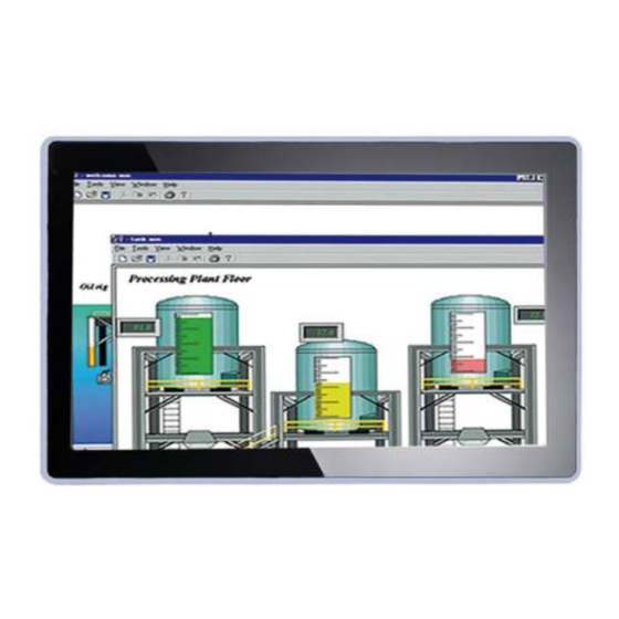
P6187W User’s Manual Chapter 1 Introduction This chapter contains general information and detailed specifications of the P6187W. Chapter 1 includes the following sections: General Description Features Specifications Dimensions and Outlines I/O Outlets Package List General Description The P6187W, an industrial 18.5 inches view area LCD Monitor comes with slim, light and reliable features to replace traditional bulky CRT for Industrial application. -
Page 6: Features
P6187W User’s Manual Features High contrast color 18.5” WXGA TFT LCD display support resolution up to 1366x768 Flat design with NEMA4/IP65-compliant Suits with resistive touch or glass High Brightness and Ultra-wide viewing angle with anti-glare features. ... -
Page 7: Dimensions And Outlines
P6187W User’s Manual Dimensions and Outlines The following diagrams show the dimensions and outlines of P6187W P6187WPC: Introduction... -
Page 8: I/O Outlets
P6187W User’s Manual I/O Outlets Please refer to the following illustration for I/O locations of the P6187W. 10 11 12 Function Function Screw type or Exit/Auto Adjust Phoenix type power input Menu (Enter function) HDMI SEL- DVI-D SEL+ Power LED Audio Port Power Switch Touch port (RS232 or USB) -
Page 9: Packing List
Adaptor x1 (for AC version only) Panel mount kit x 12 (optional) HDMI cable x1(optional) DVI cable x1 (optional) Wall mount bracket x1 (optional) If you cannot find the package or any items are missing, please contact Axiomtek distributors immediately. Introduction... - Page 10 P6187W User’s Manual This page is intentionally left blank. Introduction...
-
Page 11: Chapter 2 System Setup
P6187W User’s Manual Chapter 2 System Setup This chapter details the system parts and components with figures. Sections include: System Configuration Panel Mounting Wall Mounting VESA Mounting System Configuration The figure below shows the side views of P6187W series. Exit: Jump out the selection icon . -
Page 12: Panel Mounting
P6187W User’s Manual Panel Mounting The P6187W is designed for panel mount application. To mount the P6187W, the standard set of mounting kit (included in the system packaging) is needed. ▲P6187W Panel Mount kits Wall Mounting The P6187W provides VESA mount and wall mount. Screw four screws to fix the kit in the back chassis. -
Page 13: Vesa Mounting
P6187W User’s Manual VESA Mounting The P6187W provides VESA mount at the back of system. Screw four screws to fix the kit in the back chassis. System Setup... -
Page 14: System Jumper Setting
P6187W User’s Manual System Jumper Setting 12V DC IN 12V in only: JP3(1-3)(2-4), JP4(1-3)(2-4) 24V DC IN 24V in only: JP3(3-5)(4-6), JP4(3-5)(4-6) ★ Default Setting Jumper Jumper Setting 12V DC in (VINO-12V) (Default) Short 1-3, Short 2-4 24V DC in (VINO-12V) Short 3-5, Short 4-6 12V DC in (Default) Short 1-3, Short 2-4... -
Page 15: Appendix A Supported Input Timing Modes
P6187W User’s Manual Appendix A Supported Input Timing Modes Supported Input Timing Modes Refresh Horizontal vertical Pixel Standard Pixel Format NOTE Rate Frequency Frequency Frequency Type 640*480 60 Hz 31.5 kHz 59.94 Hz 25.175 MHz Industry Standard 72 Hz 37.9 kHz 72.80 Hz 31.500 MHz VESA Standard... - Page 16 P6187W User’s Manual This page is intentionally left blank. Supported Input Timing Modes...
-
Page 17: Appendix Bosd Operation
P6187W User’s Manual Appendix B OSD Operation Function Description of OSD Menu ※The layout and format of OSD depends on customer’s request. OSD MENU Description Luminance: Brightness Contrast Sharpness Luminance Picture Phase Clock H position ... - Page 18 P6187W User’s Manual This page is intentionally left blank. OSD Operation...


Need help?
Do you have a question about the P6187W V2 Series and is the answer not in the manual?
Questions and answers