Table of Contents
Advertisement
Quick Links
Advertisement
Table of Contents

Subscribe to Our Youtube Channel
Related Manuals for AXIOMTEK P6125


Summary of Contents for AXIOMTEK P6125
- Page 1 P6125 12.1” XGA TFT Railway Monitor User’s Manual...
-
Page 2: Disclaimers
Axiomtek does not make any commitment to update the information in this manual. Axiomtek reserves the right to change or revise this document and/or product at any time without notice. No part of this document may be reproduced, stored in a retrieval system, or transmitted, in any form or by any means, electronic, mechanical, photocopying, recording, or otherwise, without the prior written permission of Axiomtek Co., Ltd. -
Page 3: Safety Precautions
Most electronic components are sensitive to static electrical charge. Disconnect the power cords from the P6125 Series before making any installation. Be sure both the system and the external devices are turned OFF. Sudden surge of power could damage sensitive components. Make sure the P6125 Series is properly grounded. -
Page 4: Table Of Contents
Table of Contents Disclaimers ...................... i Safety Precautions ..................iii Chapter 1 Introduction ..........1 General Description ................1 Features ....................2 Specifications ..................2 Dimensions and Outlines ..............3 I/O Outlets .................... 4 Packing List ..................5 Chapter 2 System Setup .......... -
Page 5: Chapter 1 Introduction
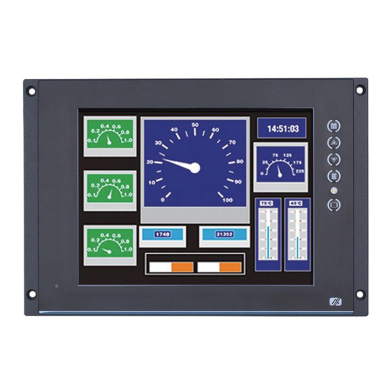
Package List General Description The P6125 is a 12.1-inch view area industrial LCD monitor that incorporates a slim, lightweight display to replace traditional bulky CRT monitors for Industrial applications, with a unique flat design specifically suited for panel mounting and VESA mounting. Its display interface... -
Page 6: Features
Mounting: Supports panel mount and VESA arm mount Net weight P6125: 2.2 KGS Dimension (main body size) P6125: 330 x 245 x 57 mm Operation temperature -25°C to 55°C Relative humidity 20% to 90% @ 40°C, Non-condensing ... -
Page 7: Dimensions And Outlines
P6125 User’s Manual Dimensions and Outlines The following diagrams show the dimensions and outlines of the P6125. Introduction... -
Page 8: I/O Outlets
P6125 User’s Manual I/O Outlets Please refer to the following illustrations for I/O locations of the P6125. I/O outlets with VGA input and speaker Function Function Menu (Enter function) Touch & remote control via RS-232 SEL+ SEL- HDMI Menu Exit / Input Switch... -
Page 9: Packing List
P6125 User’s Manual Packing List When you receive the P6125 VGA input version, the bundled package should contain the following items: P6125 unit x 1 VGA cable x 1 RS-232 cable x1 (for resisitve touch) If you request a cable assembly for resistive touch and remote control, please refer to section 2.4: I/O Pin Assignment. - Page 10 P6125 User’s Manual This page is intentionally left blank. Introduction...
-
Page 11: Chapter 2 System Setup
P6125 User’s Manual Chapter 2 System Setup This chapter details the system parts and components with figures. Sections include: System Configuration Panel Mounting VESA Mounting I/O Pin Assignment DC power Waterproof power cable ... -
Page 12: System Configuration
P6125 User’s Manual System Configuration The figure below shows the side views of the P6125 series. Menu: Press this button to turn on/off the OSD (on-screen display) main menu. Press this button to activate selected items. SEL+: To scroll up the menu. -
Page 13: Panel Mounting
The P6125 is designed for panel mount applications. To mount the P6125, locate the standard holes on the front of P6125. VESA Mounting The P6125 provides VESA mount at the back of system. Screw four screws to fix the kit in the back chassis. System Setup... -
Page 14: I/O Pin Assignment
P6125 User’s Manual I/O Pin Assignment The P6125 comes with a DC-in connector, T/S port, HDMI port, DVI-D port, and Line-In port. Please refer to following information for detailed pin assignment. 2.4.1 DC power jack w/ M12 connector, 24~110VDC power input... -
Page 15: Vga Port
P6125 User’s Manual 2.4.3 VGA port Define Define Define Red GND N.C. Green Green GND DDC Data Blue Blue GND H-Sync N.C. +5V (In) V-Sync Ground Ground DDC Clock 2.4.4 RS 232 port: supports multi-functions of T/S and remote Define... -
Page 16: Y Cable For Rs-232 To Resistive Touch And Remote
P6125 User’s Manual 2.4.5 Y cable for RS-232 to resistive touch and remote DB9: connects to P6125 DB9 male: connects to P6125 Define Define Remote RXD Touch DTR Touch TXD Touch RTS Touch RXD Remote TXD Touch DSR N.C. Ground... -
Page 17: Hdmi Port
P6125 User’s Manual 2.4.6 HDMI port Define Define Define TMDS2+ DDC clock Cable Detect (GND) TMDS0- DDC date TMDS2- TMDS clock+ TMDS1+ Vin (+5V) TMDS clock- Hot plug detect TMDS1- N.C. TMDS0+ N.C. 2.4.7 DVI-D port Define Define Define Define TMDS2−... - Page 18 P6125 User’s Manual This page is intentionally left blank. System Setup...
-
Page 19: Appendix A Supported Input Timing Modes
P6125 User’s Manual Appendix A Supported Input Timing Modes Horizontal Timing Vertical Timing Pixel SPEC Tota Freq. Freq. Total Active Freq. Active MODE Sync Sync Polar Polar Pixel Pixel Line Line 640×480 25.175 31.469 59.940 @60Hz VESA 640×480 25.175 31.469 59.940... - Page 20 P6125 User’s Manual This page is intentionally left blank. Supported Input Timing Modes...
-
Page 21: Appendix Bosd Operation
P6125 User’s Manual Appendix B OSD Operation Function Description of OSD Menu ※ The OSD layout and format depend on customer requests. Icon Description Luminance: Brightness Contrast Sharpness Ambient Sense Luminance Color: Color Temperature (9300,7500,6500,user) ... - Page 22 P6125 User’s Manual This page is intentionally left blank. OSD Operation...
-
Page 23: Appendix C Ad Board Management System
P6125 User’s Manual Appendix C AD Board Management System Digital Signage System Control Tool Files: ADS_Client.exe: main application ADS_RS-232_x32.dll / ADS_RS-232_x64.dll: library for application reference. The files must be manually copied to System_Disk (C:):\Windows\System32 or installed with ADS_Client.exe ... - Page 24 P6125 User’s Manual Application UI and functions When the application is executed, it will auto scan all serial ports to find the correct port to which you connect the AD Board. If the application cannot find the serial port the AD Board connects to, you need to ...
- Page 25 P6125 User’s Manual Control items Brightness Control: scroll bar Range: 0 ~ 100 Remark: if getting or setting fails, the application will show “Brightness - Failed” Contrast Control: scroll bar Range: 0 ~ 100 Remark: if getting or setting fails, the application will show “Contrast -...
- Page 26 P6125 User’s Manual Backlight MIN: Control: drop-down list Range: 0 ~ 100 Remark: this value cannot be bigger than value of Backlight MAX Remark: if getting or setting fails, the application will show “Backlight MIN - Failed”...
- Page 27 P6125 User’s Manual Dim: (Option) Control: button Way: ON and OFF Remark: if setting fails, the application will show “Auto-Dimming - Failed” Remark: if there is no Auto-Dimming, it will show “Auto-Dimming - Disable” 10. Adjust: ...
- Page 28 P6125 User’s Manual This page is intentionally left blank. AD Board Management System...
Need help?
Do you have a question about the P6125 and is the answer not in the manual?
Questions and answers