Table of Contents

Related Manuals for Aaeon SBC-456


Summary of Contents for Aaeon SBC-456
-
Page 2: Fcc Statement
FCC STATEMENT THIS DEVICE COMPLIES WITH PART 15 FCC RULES. OPERA- TION IS SUBJECT TO THE FOLLOWING TWO CONDITIONS: (1) THIS DEVICE MAY NOT CAUSE HARMFUL INTERFER- ENCE. (2) THIS DEVICE MUST ACCEPT ANY INTERFERENCE RECEIVED INCLUDING INTERFERENCE THAT MAY CAUSE UNDESIRED OPERATION. - Page 3 This document is copyrighted, 1998, by AAEON Technology Inc. All rights are reserved. AAEON Technology Inc. reserves the right to make improvements to the products described in this manual at any time without notice. No part of this manual may be reproduced, copied, translated, or transmitted in any form or by any means without the prior written permission of AAEON Technology Inc.
- Page 4 Dear Customer, Thank you for purchasing the SBC-456/456E board. The user manual is designed to help you get the most out of the SBC-456/ 456E, please read it thoroughly before you install and use the board. The product that you have purchased comes with a one- year warranty, but AAEON cannot be responsible for misuse of the product.
-
Page 5: Table Of Contents
Introduction ................2 Features .................. 3 Specifications ................. 4 Board layout ................6 Card dimensions ..............7 Jumpers and connectors ............ 10 Locating jumpers and connectors ........11 Setting jumpers ..............12 Safety precautions ............... 13 Installing DRAM (SIMMs) ..........14 Installing SIMMs .............. - Page 6 Reserved IR connector (J5) ..........26 Clear CMOS (J6) ..............27 Power LED and keylock (J7) ..........27 Fan power connector (J8) ..........28 LCD SHF/ASHF clock selections (JP1) ......28 LCD panel's voltage setting (JP2) ........29 DOC address setting (JP3) ..........29 Hardware reset (JP4) ............
- Page 7 Software drivers ..............66 Hardware configuration ............66 Necessary prerequisites ............67 Before you begin ..............67 WindowsÔ Ô Ô Ô Ô 95 ..............68 WindowsÔ Ô Ô Ô Ô 3.1 ..............69 Changing color schemes............70 DOS ..................70 Driver installation - DOS Setup ..........
-
Page 9: Specifications
This chapter provides background information for the SBC-456/456E. Sections include: • Card specifications • Board layout Chapter 1 General Information... -
Page 10: Features
DiskOnChip is available in capacities from 2MB to 72MB and fits in a standard 32-pin DIP socket. Another feature of the SBC-456/456E is the inclusion of a high speed, local bus IDE controller. This controller supports (through ATA PIO) mode 3 and mode 4 hard disks, enabling data transfer rates in excess of 11 MB/second. - Page 11 You can change the display BIOS or install a boot ROM simply by programming the Flash chip. The SBC-456/456E supports 5 V EDO DRAM. It also provides two 72- pin SIMM (Single In-line Memory Module) sockets for its onboard system DRAM.
- Page 12 Ethernet controller (for 456E): Realtek RTL8029AS 10-BaseT PCI-Bus Ethernet controller Ethernet interface (for 456E): Software drivers available. Supports remote boot ROM function SSD interface: One 32-pin DIP socket supports the M-Systems DiskOn- Chip 2000 series, memory capacity from 2MB to 72MB SBC-456/456E User Manual...
- Page 13 Power supply voltage: +5V (4.75V to 5.25V) +12V (11.4V to 12.6V) Max. power Requirement: +5V @ 3A ° ° Operating temperature: 32 to 140 F (0 to 60 Board size: 7.3" (L) x 4.8" (W) (185 mm x 122 mm) Weight: 0.23 kg Chapter 1 General Information...
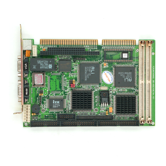
- Page 14 20F001N 9623GX RTL8029AS CHIPS FS65550 Am486TMDX5-133V 168HC P/N: 1907456001 SBC-456 Rev.A1.1 SBC-456/456E User Manual...
- Page 15 17.8 21.5 80.65 98.5 19.5 P/N: 1907456001 SBC-456 Rev.A1.1 122.00 Chapter 1 General Information...
- Page 16 SBC-456/456E User Manual...
- Page 17 This chapter explains set up procedures for the SBC-456/456E hardware, including instructions on setting jumpers and connecting peripherals, switches and indicators. Be sure to read all safety precautions before you begin the installa- tion procedure. Chapter 2 Installation...
-
Page 18: Jumpers And Connectors
Ethernet link signal LED Ethernet active signal LED Buzzer or external speaker Reserved IR connector Clear CMOS Power LED & keylock Fan power connector LCD SHF/ASHF clock select LCD panel voltage setting DOC address setting Hardware reset RS232/422/485 select SBC-456/456E User Manual... -
Page 19: Chapter 2 Installation
JP 2 JP 3 CN 3 CHIPS FS65550 CN 2 JP 1 CN 1 A m 4 8 6 T M D X 5 - 1 3 3 V 1 6 8 H C P/N: 1907456001 SBC-456 Rev.A1.1 Chapter 2 Installation... - Page 20 A pair of needle-nose pliers may be helpful when working with jumpers. If you have any doubts about the best hardware configuration for your application, contact your local distributor or sales representa- tive before you make any changes. SBC-456/456E User Manual...
- Page 21 Warning! Always completely disconnect the power cord from your chassis whenever you are working on it. Do not make connections while the power is on because sensitive electronic components can be damaged by the sudden rush of power. Only experienced electronics personnel should open the PC chassis.
- Page 22 The SBC-456/456E CPU card provides two 72-pin SIMM (Single In- line Memory Module) sockets and supports between 4MB and 64MB. When installing SIMMs, make sure that Bank 1 is filled first. Note: that the modules can only fit into a socket one way.
- Page 23 You can attach two Enhanced Integrated Device Electronics hard disk drives to the SBC-456/456E's internal controller. The card comes with a 40-pin flat piggyback cable. This cable has three identical 40-pin flat-cable connectors. Wire number 1 on the cable is red or blue, and the other wires are gray.
- Page 24 IORDY BALE N.C. IRQ 14 -I/O CS16 N.C. -ACT You can connect an LED to indicate that an IDE device is in use. The pin assignments for this jumper are as follows: Signal -R/W IDE Pull high SBC-456/456E User Manual...
- Page 25 The SBC-456/456E CPU card's SVGA connector (CN9) with PCI bus supports monochrome display as well as high resolution color displays. The card also features an LCD connector (CN2), which allows you to connect various flat panel displays. The following table lists their pin assignments:...
- Page 26 Signal Signal +12 V +12 V +5 V +5 V EN VEE SHFCLK FLM (V SYS) LP (H SYS) ENABKL SBC-456/456E User Manual...
- Page 27 You can attach up to two floppy disks to the SBC-456/456E's on- board controller. You can use any combination of 5 1/4" (360 KB and 1.2 MB) and/or 3 1/2" (720 KB, 1.44 MB, and 2.88 MB) drives. The SBC-456/456E CPU card comes with a 34-pin daisy-chain drive connector cable.
- Page 28 Normally, the parallel port is used to connect the card to a printer. The SBC-456/456E includes an onboard parallel port, accessed through the CN4 connector, a 26-pin flat-cable connector. The CPU card comes with an adapter cable, which lets you use a traditional DB-25 connector.
- Page 29 In single board computer (non-passive backplane) applications, you will need to connect the power directly to the SBC-456/456E board using CN5. This connector is fully compatible with the standard PC PS/2 power supply connector, P8. See the following table for its pin assignments: Signal N.C.
- Page 30 BIOS Peripheral Setup program. The card mounting bracket holds COM 1, the DB-9 serial port connector for the first port. The connector on the SBC-456/456E board (CN6) is COM 1 and COM 2 for RS-232/422/485. The following sections tell how to make connections.
- Page 31 Signal B485TXD+ B485TXD- B422RXD+ B422RXD- Chapter 2 Installation...
- Page 32 10-pin polarized header (CN7). For 10Base-T RJ-45 operation, an adapter cable converting CN7 into a standard RJ-45 jack is required. The SBC-456/456E board provides two keyboard and PS/2 mouse connectors. A 5-pin connector (CN10) supports passive backplane applications. A second 6-pin mini-DIN keyboard and PS/2 mouse connector (CN11) on the card mounting bracket supports single board computer applications.
- Page 33 Function K.B. data PS/2 mouse data +5 V K.B. clock PS/2 mouse clock The SBC-456E supports two sets of LED connectors for external LEDs. A continuously lit LED indicates good linkage between the SBC- 456E and its supporting hub. A flashing LED indicates that the SBC-456E is transmitting or receiving data.
- Page 34 EXT SPK. Enabling the external speaker automatically disables the internal buzzer. Buzzer External Speaker 1 2 3 4 1 2 3 4 1 2 3 4 Function Speaker output Buzzer in Speaker output Function IR_TX IR_RX FIR_RX SBC-456/456E User Manual...
- Page 35 You can connect an external switch to clear the CMOS. This switch closes J6 and turns on the power, at which time the CMOS setup will be cleaned. Protect (default) Clear CMOS You can connect an LED to indicate when the CPU card is on. Pin 1 of J7 supplies power to the LED;...
- Page 36 You can connect a fan to the CPU. SBC456/456E offer +5V to drive a fan for CPU. You can select the LCD control signals by setting JP1. The following charts show the available options. SHF CLK from C&T65550* ASHF CLK from SHF CLK * default SBC-456/456E User Manual...
- Page 37 You can select the LCD connector (CN2) driving voltage by setting JP2. The configuration is as follows: 3.3 V 5 V(default) 2 4 6 1 3 5 1 3 5 The DiskOnChip 2000 occupies a 8 KB window in the upper memory address range of C800 to E000.
- Page 38 The following table shows the pin assign- ments for JP4. Function Ground Reset The SBC-456/456E offers two serial ports. One RS-232 (CN8) and one RS-232/422/485 (CN6). The follwing charts show the available options: *RS-232 RS-422...
- Page 39 The DiskOnChip 2000 family of products provides a single chip solid-state flash disk in a standard 32-pin DIP package. The DiskOnChip 2000 is a solid-state disk with no moving parts, resulting in a significant reduction in power consumption and an increase in reliability.
- Page 40 SBC-456/456E User Manual...
- Page 41 This chapter describes the card’s diagnos- tic tests and how to set BIOS configura- tion data in a Windows environment. Chapter 3 AMIBIOS setup...
- Page 42 As POST executes, the following appears; Hit <DEL> if you want to run SETUP Press <DEL> to run AMIBIOS setup. The AMIBIOS setup screen appears as follows: SBC-456/456E User Manual...
- Page 43 AMIBIOS Setup can be accessed via keyboard, mouse, or pen. The mouse click functions are: • single click to change or select both global and current fields • double click to perform an operation in the selected field AMIBIOS Setup has a built-in keyboard driver that uses simple keystroke combinations: Keystroke Function...
- Page 44 Mode. All parameters relate to IDE drives except Type. Date, Day and Time Configuration Select the Date and Time icon in the Standard setup. The current values for each category are displayed. Enter new values through the keyboard. SBC-456/456E User Manual...
- Page 45 Floppy A, Floppy B Select these icons to configure the type of floppy drive that is attached to the system: 360 KB 5 1/4", 1.2 MB 5 1/4", 720 KB 3 1/2", 1.44 MB 3 1/2", and/or 2.88 MB 3 1/2". The settings have not been pre-installed.
-
Page 46: Advanced Setup
Select the Advanced icon from the AMIBIOS Setup main menu to enter Advanced setup. The "Advanced Setup" options described in this section are the standard options as shown on the following screen. SBC-456/456E User Manual... - Page 47 Quick Boot: Set this option to Enabled to instruct AMIBIOS to boot quickly when the computer is powered on. This option replaces the old Above 4 MB Memory Test Advanced Setup option. Setting Description Disabled AMIBIOS test all system memory. AMIBIOS waits up to 40 seconds for a READY signal from the IDE hard disk drive.
- Page 48 EGA/VGA, or Absent. The default setting is EGA/VGA. Display Device: This option allows user to select display device. The settings are CRT, LCD, and Both. The default setting is Both. LCD type This option allows user to select the LCD type. SBC-456/456E User Manual...
- Page 49 The SBC456/456E supports the following LCD types: s t i Password Check: This option enables password checking every time the computer is powered on or every time AMIBIOS Setup is executed. If Always is chosen, a user password prompt appears every time the computer is turned on.
- Page 50 The contents of C0000h - C3FFFh are written to the same Neither L1 internal cache memory on the nor L2 secondary cache memory is enabled. WriteThru Use the write-through caching algorithm. WriteBack Use the write-back caching algorithm. SBC-456/456E User Manual...
- Page 51 System BIOS Cacheable When this option is set to Enabled, the contents of the F0000h system memory segment can be read from or written to L2 cache memory. The contents of the F0000h memory segment are always copied from the BIOS ROM to system RAM for faster execution. The settings are Enabled or Disabled.
- Page 52 ROM area. Also, the contents of the RAM area can be read from and written to cache memory. Disabled The video ROM is not copied to RAM. The contents of the video ROM cannot be read from or written to cache memory. SBC-456/456E User Manual...
- Page 53 The AMIBIOS Setup options deccribed in this section are selected by choosing the Chipset icon from the AMIBIOS setup main menu, shown below. The following is an option list offered by Chipset Setup Function Options Auto Configuration Function Disabled/Enabled AT Bus Clock 7.16 CPU Bus Speed/3 CPU Bus Speed/4...
- Page 54 Disabled Enabled ISA I/O Recovery Time 0.5 ms 1.0 ms 1.5 ms 2.0 ms 2.5 ms 3.0 ms 3.5 ms System Hidden Refresh 15 ms 30 ms 60 ms 120 ms Cx586 Linear Wrapped Mode Disabled Enabled SBC-456/456E User Manual...
- Page 55 The Power Management Setup offers options to help reduce power consumption. To see the options in this group, choose the Power Management Setup icon from the AMIBIOS Setup main menu. Power Management Mode/APM Funtion (Advanced Power Management) Set this option to Enabled to enable the power management and APM (Advanced Power Management) features.
- Page 56 If your change the setting "Power Management mode" from Disabled to Enabled, the picture bellow is shown: SBC-456/456E User Manual...
- Page 57 PCI/PnP Setup options are displayed by choosing the PCI/PnP Setup icon from the AMIBIOS Setup main menu. All PCI/PnP Setup options are described in this section. Onboard VGA Enabled AMIBIOS supports this function. If users put another VGA card in one of the PCI slots. Then the VGA Card has a higher priority than onboard VGA.
- Page 58 IDE controller on the motherboard is automatically disabled. The settings are Disabled, Auto, Slot1, Slot2, Slot3, or Slot4. If Auto is selected, AMIBIOS automatically determines the correct setting for this option. The Optimal and Fail-Safe default settings are Auto. SBC-456/456E User Manual...
- Page 59 PCI Slot1 IRQ Priority PCI Slot2 IRQ Priority PCI Slot3 IRQ Priority PCI Slot4 IRQ Priority This option sets PCI slot IRQ priority. The settings are Auto, 3, 4, 5, 7, 9, 10, 11. The default setting is Auto. Chapter 3 AMIBIOS setup...
- Page 60 PCI/PnP Setup options to remove the IRQ by assigning the option to the ISA/EISA setting. Onboard I/O is configurable by AMIBIOS. The IRQs used by onboard I/O are configured as PCI/PnP. The settings are PCI/PnP or ISA/EISA. The default settings are PCI/PnP. SBC-456/456E User Manual...
- Page 61 Reserved Memory Size This option specifies the size of the memory area reserved for legacy ISA adapter cards. The settings are Disabled, 16K, 32K, and 64K. The default settings are Disabled. Reserved Memory Address This option specifies the beginning address (in hex) of the reserved memory area.
- Page 62 Onboard Serial Port 1 This option enables serial port 1 on the motherboard and specifies the base I/O port address for serial port 1. The settings are Auto, Disabled, 3F8h, 3E8h, 2E8h, and 2F8h. The Fail-Safe default setting is Auto. SBC-456/456E User Manual...
- Page 63 Onboard Serial Port2 This option enables serial port 2 on the motherboard and specifies the base I/O port address for serial port 2. The settings are Auto. Disabled, 3F8h, 2F8h, 3E8h, and 2E8h. The default setting is Auto. Onboard Parallel Port This option enables the parallel port on the motherboard and specifies the parallel port base I/O port address.
- Page 64 IRQ7 is used for the Parallel Port (LPT 1). The IRQ can be changed to IRQ5. Onboard IDE This option specifies the onboard IDE controller channels that will be used. The settings are Primary, Both, or Disabled. SBC-456/456E User Manual...
- Page 65 The following icons appear in this section: Two Levels of Passwords Both the Supervisor and the User icons configure password support. If you use both, the Supervisor password must be set. If this feature is enabled, you can select AMIBIOS. The setup messages are in different languages.
- Page 66 To assign a password, 1. Enter a 1-6 character password. The password does not appear on the screen when typed. 2. Retype the password when prompted by AMIBIOS. A message box will appear when the password is confirmed. SBC-456/456E User Manual...
- Page 67 Keep a record of the password. If you forget the password, you must reset CMOS RAM and reconfigure the system. Changing a password 1. Select the Supervisor or User icon from the Security section of the AMIBIOS Setup main menu. 2.
- Page 68 The following is displayed after any attempt to format any cylinder, head, or sector of any hard disk drive via the BIOS INT 13 Hard Disk Drive Service: Format !!! nue (Y/N)? _ Possible VIRUS: Conti SBC-456/456E User Manual...
- Page 69 The following icons appear in this section: Detect IDE: If drive C is an IDE drive, the hard disk drive parameters for drive C: are automatically detected and reported to the Hard Disk Drive C screen in Standard Setup, so that you can easily configure drive C. Drive D and the CD-ROM could also be automatically detected and reported to screen if drive D and CD-ROM are IDE drives.
-
Page 70: Original
You can load the Fail-Safe AMIBIOS Setup options settings by selecting the Fail-Safe icon. The Fail-Safe settings provide the most stable settings, though they do not provide optimal performance. Use this option as a diagnostic aid if the system is behaving erratically. SBC-456/456E User Manual... -
Page 71: Amibios Main Menu
You can exit AMIBIOS by pressing the <ESC> key while in the AMIBIOS main menu screen. The following screen appears: Select the option you desire, and the system will continue its boot up sequence. Chapter 3 AMIBIOS setup... - Page 72 SBC-456/456E User Manual...
-
Page 73: Utility
This chapter provides information about: • Driver types and installation • Software utility installation and use Chapter 4 Flat Panel/CRT Controller... - Page 74 2. If a high-resolution mode is not supported on your system, try using a lower-resolution mode. For example, 1024 x 768 mode will not work on some systems, but 800 x 600 mode is supported on most. SBC-456/456E User Manual...
- Page 75 The instructions in this manual assume that you understand elementa- ry concepts of MS-DOS and the IBM Personal Computer. Before you attempt to install any driver or utility, you should: • Know how to copy files from a floppy disk to a directory on the hard disk •...
- Page 76 3. Once the installation is complete, the Change Display Type window will reappear. Click on Close to close the window. Then the Display Properties window will reappear. Click on Apply. Restart the system for the new settings to take effect. SBC-456/456E User Manual...
- Page 77 Ô Ô Ô Ô Ô These drivers are designed to work with Microsoft Windows Version 3.1. You may install these drivers either through WindowsÔ or in DOS. 1. Install Windows as you normally would for a VGA display. Run Windows to make sure that it is working correctly. 2.
-
Page 78: Default
Windows configuration. Use the Up arrow key to move to the Display line and press <ENTER>. 8. A list of display drivers will be shown. Use the arrow keys to select one of the drivers starting with an asterisk (*) and press <ENTER>. SBC-456/456E User Manual... - Page 79 9. Follow the directions on the screen to complete the setup. In most cases, you may press <ENTER> to accept the suggested option. When Setup is done, it will return to DOS. Type WIN <ENTER> to start Windows with the new display driver. To change display drivers from DOS, change to the Windows directory and run Setup, repeating steps 4 and 5 from the previous page.
- Page 80 DOS Full Screen or OS/2 Full Screen session. 3. Do not start WIN-OS/2 in a DOS or OS/2 Window. The system does not support the enhanced video mode being used in a window, and therefore will not run. SBC-456/456E User Manual...
- Page 81 4. When running WIN-OS/2, DO NOT use <ALT>+<HOME> to switch a DOS or OS/2 Full Screen session to Windows. If this happens, do a system shutdown and reboot. NOTE: Diskette copies of the OS/2 drivers must have a VOLUME LABEL that reads “DISP 1” in order to be an installable diskette.
- Page 82 A color test screen should appear, followed by the Testing Mode window. Click on Yes to contiune. The Display Settings Change window will appear. Click on Restart Now for the new settings to take effect. SBC-456/456E User Manual...
- Page 83 Ô Ô Ô Ô Ô 1. Install Windows NT4.0 as you normally would for a VGA display. First click the Start button, go to Settings and click on Control Panel. Choose the Display icon and click on the icon. In the Display Properties window, click on the Settings tab.
-
Page 84: Software Utilities
Refresh. DISPLAY DEVICE allows you to select the display type from the following: • CRT Only <ALT C> • LCD (Flat Panel) only <ALT I > • Both CRT and LCD (Flat Panel) <ALT B> SBC-456/456E User Manual... - Page 85 REFRESH RATE allows you to select the refresh rate from the following: • Interlaced • 56 Hz • 60 Hz • 70 Hz • 72 Hz • 75 Hz • 85 Hz The refresh rate is available in CRT Mode only. Note: 1.
- Page 86 COLOR <ALT O> allows you to select the number of colors from the following: • 16 (4bits per pixel) • 256 (8 bpp) • 32K (15 bpp) • 64K (16 bpp) • 16M (24 bpp) By selecting the color depth first, will be displayed the allowable resolutions. SBC-456/456E User Manual...
- Page 87 DPI<ALT P> allows you to select a large or small font. DISPLAY<ALT D> allows you to select the display type from the following: • CRT only • LCD (Flat Panel) only • Both CRT and LCD (Flat Panel) MONITOR SELECTION <ALT M> allows you to select from the list of monitors.
- Page 88 SBC-456/456E User Manual...
- Page 89 This chapter describes how to configure the Etherent Card to match your applica- tion requirements (SBC-456E only). Chapter 5 Software Configuration...
- Page 90 The Ethernet Setup Menu also offers three very useful diagnos- tic functions. These are: 1. Run EEPROM test 2. Run Diagnostics on Board 3. Run Diagnostics on Network Each option has its own display screen which shows the format and result of any diagnostic tests undertaken. SBC-456/456E User Manual...
- Page 91 The following demo program illustrates the programming steps required to enable, set, and disable the watchdog timer.
- Page 92 -- access the I/O port 0x443, e.g. outportb(0x80, 0); // disable watchdog timer inportb(0x443); // refresh watchdog timer * note: if you want to refresh the watchdog timer, you have to disable it first. A-84 SBC-456/456E User Manual...
- Page 93 outportb(0x444, 0): // set time-out event to reset-system outportb(0x443x 10); // set time-out interval to 10 seconds iutportb(0x443); // enable watchdog timer customer_job(); // execute your job here, be sure your job will finished within 10 seconds outportb(0x80, 0); // refresh watchdog timer, otherwise the system will reset after time-out outputb(0x443, 20);...
- Page 94 A-86 SBC-456/456E User Manual...
-
Page 95: Installing Pc/104 Modules
This appendix gives instructions for installing PC/104 modules. Appendix B Installing PC/104 Modules B-87... - Page 96 The SBC-456/456E's PC/104 connectors give you the flexibility to attach PC/104 expansion modules. These modules perform the functions of traditional plug-in expansion cards, but save space and valuable slots. Modules include: • PCM-3110B PCMCIA Module (one-slot) • PCM-3115B PCMCIA Module (two-slot) •...
- Page 97 Installing these modules on the SBC-456/456E is a quick and simple operation. The following steps show how to mount the PC/104 modules: Step1 Remove the SBC-456/456E from your system, paying particular attention to the safety instructions already mentioned above. Step2 Make any jumper or link changes required to the CPU card now.
- Page 98 0.300 3.250 3.775 3.575 3.575 0.200 0.200 3.350 0.200 3.550 B-90 SBC-456/456E User Manual...
Need help?
Do you have a question about the SBC-456 and is the answer not in the manual?
Questions and answers