
Subscribe to Our Youtube Channel
Related Manuals for Aaeon SBC-411


Summary of Contents for Aaeon SBC-411
- Page 2 FCC STATEMENT THIS DEVICE COMPLIES WITH PART 15 FCC RULES. OPERA- TION IS SUBJECT TO THE FOLLOWING TWO CONDITIONS: (1) THIS DEVICE MAY NOT CAUSE HARMFUL INTERFER- ENCE. (2) THIS DEVICE MUST ACCEPT ANY INTERFERENCE RECEIVED INCLUDING INTERFERENCE THAT MAY CAUSE UNDESIRED OPERATION.
- Page 3 This document is copyrighted, 1998, by AAEON Technology Inc. All rights are reserved. AAEON Technology Inc. reserves the right to make improvements to the products described in this manual at any time without notice. No part of this manual may be reproduced, copied, translated, or transmitted in any form or by any means without the prior written permission of AAEON Technology Inc.
- Page 4 Dear Customer, Thank you for purchasing the SBC-411/411E board. The user manual is designed to help you get the most out of the SBC-411/ 411E,please read it thoroughly before you install and use the board. The product that you have purchased comes with a one-year warranty, but AAEON cannot be responsible for misuse of the product.
- Page 5 Introduction ................2 Features .................. 3 Specifications ................. 4 Board layout ................6 Card dimensions ..............7 Jumpers and connectors ............ 10 Locating jumpers and connectors ........11 Setting jumpers ..............12 Safety precautions ............13 Installing DRAM (SIMMs) ..........14 Installing SIMMs ..............
-
Page 6: Table Of Contents
DOC address setting (JP2) ..........24 Clear CMOS (JP3) ............. 24 DsikOnChip socket (U10) ..........25 General information ............28 Starting AMIBIOS setup ............28 AMIBIOS main menu ............. 28 Using a mouse with AMIBIOS setup ........29 Using the keyboard with AMIBIOS setup ......29 Standard Setup .............. - Page 7 This chapter gives background informa- tion on the SBC-411/411E. Sections include: • Card specifications • Board layout Chapter 1 General Information...
- Page 8 2MB to 72MB and fits in a standard 32-pin DIP socket. Another feature of the SBC-411/411E is the inclusion of a high speed, local bus IDE controller. This controller supports (through ATA PIO) mode 3 and mode 4 hard disks, enabling data transfer rates in excess of 11 MB/ second.
- Page 9 BIOS or install a boot ROM simply by program- ming the Flash chip. The SBC-411/411E supports 5 V EDO DRAM. It also provides one 72- pin SIMM (Single In-line Memory Module) sockets for its onboard system DRAM. These sockets give you the flexibility to configure your system from 4 MB to 32 MB of DRAM using the most economi- cal combination of SIMMs.
- Page 10 PC/104 connector: 104-pin connector for a 16-bit bus Watchdog Timer: Can generate a system reset or IRQ15. The time interval is software selectable (2sec~128min, 1sec/step) DMA channels: 7 Interrupt levels: 15 Power management: I/O Peripheral devices support power saving and doze/ standby/suspend modes SBC-411/411E User Manual...
- Page 11 Power supply voltage: +5V (4.75V to 5.25V) +12V (11.4V to 12.6V) Max. power requirement: +5V @ 3A ° ° Operating temperature: 32 to 140 F (0 to 60 Board size: 7.3"(L) x 4.8"(W) (185mm x 122mm) Weight: 0.23 kg Chapter 1 General Information...
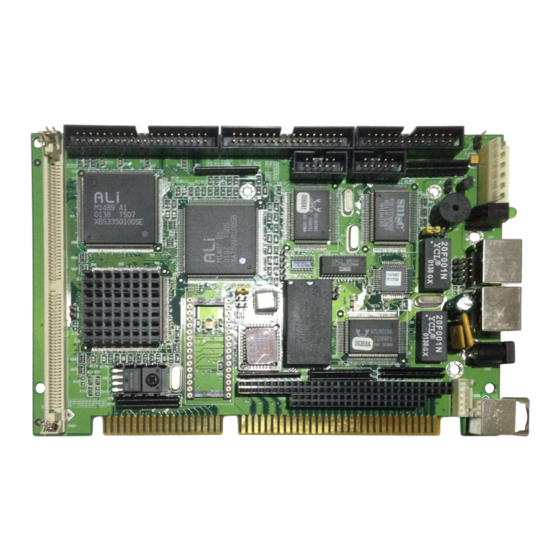
- Page 12 PCI 10Base-T Power Keyboard connector Parallel port connector PC-104 COM2 connector COM1 M48T86PCI RTL8029AS AMI Flash interface BIOS Socket for Chipset DiskOnChip connector AMD 486 DX5-133 CPU Chipset Up to 32MB DRAM SBC-411/411E User Manual...
- Page 13 98.50 27.1 21.7 80.51 5.11 98.50 19.50 122.00 Chapter 1 General Information...
- Page 14 SBC-411/411E User Manual...
- Page 15 This chapter describes how to set up the SBC-411/411E hardware, including instructions on setting jumpers and connecting peripherals, switches, and indicators. Be sure to read all safety precautions before you begin the installa- tion procedure. Chapter 2 Installation...
-
Page 16: Doc Address Setting (Jp2)
IDE LED connector Int/Ext buzzer Ethernet link signal LED Ethernet active signal LED Power LED & KB_LOCK J7 (optional) LED_LINK ISA 10Base-T J8 (optional) LED_RX ISA 10Base-T CPU fan power connector Reset switch DOC address setting Clear CMOS 10 SBC-411/411E User Manual... - Page 17 (SBC-411E only) PCI 10-BaseT Power (optional)ISA 10-BaseT connector RJ-45 Jack connector RJ-45 Jack (CN8) (CN11) (CN7) CN10 internal keyboard Parallel Port PC/104 Connector (CN3) connector COM 2 (CN6) COM 1 (CN5) M48T86PCI RTL8029AS AMI Flash Connector BIOS (CN2) connector (CN1) Up to 32MB DRAM Chapter 2 Installation...
- Page 18 If you have any doubts about the best hardware configuration for your application, contact your local distributor or sales representa- tive before you make any changes. Generally, you simply need a standard cable to make most connec- tions. 12 SBC-411/411E User Manual...
- Page 19 Warning! Always completely disconnect the power cord from your chassis whenever you are working on it. Do not make connections while the power is on, sensitive electronic components can be damaged by the sudden rush of power. Only experienced electronics personnel should open the PC chas- sis.
- Page 20 The SBC-411/411E CPU card provides one 72-pin SIMM (Single In- line Memory Module) socket and supports between 4 MB to 32 MB of RAM. Note: that the modules can only fit into a socket one way. 1. Insert the memory module into the socket at a moderate angle.
- Page 21 You can attach up to two Enhanced Integrated Device Electronics (IDE) hard disk drives to the SBC-411/411E internal controllers. The card comes with a 40-pin cable. Wire number 1 on the cable is red or blue, and the other wires are gray.
- Page 22 The following table lists the pin numbers and their respective signals: Signal Signal Reset N.C. N.C. IORDY BALE N.C. -I/O CS16 N.C. -ACT 16 SBC-411/411E User Manual...
- Page 23 You can attach up to two floppy disks to the SBC-411/411E/486's onboard controller. You can use any combination of 5.25" (360 KB and 1.2 MB) and/or 3.5" (720 KB, 1.44 MB, and 2.88 MB) drives. The CPU card comes with a 34-pin daisy-chain drive connector cable.
- Page 24 Normally, the parallel port is used to connect the card to a printer. The SBC-411/411E includes an onboard parallel port, which is accessed through a 26-pin flat-cable connector. The CPU card comes with an adapter cable, which lets you use a traditional DB-25 connector.
- Page 25 In SBC (non-passive backplane) applications you will need to connect power directly to the SBC-411/411E board using CN4. CN4 is fully compatible with the standard PC power supply connector. See the following table for its pin assignments: Function N.C. +5 V...
- Page 26 A 10Base-T RJ-45 connector (CN7) ethernet adapter cable connects to CN7 on the SBC-411E. The SBC-411/411E board provides two keyboard connectors. A 5- pin connector supports passive backplane applications. A second 6-pin mini-DIN connector on the card mounting bracket supports SBC applications.
- Page 27 You can connect a LED to indicate when the CPU card is on. Function LED Power (+5V) Ground You can connect a LED to indicate that an IDE device is in use. The pin assignments for this jumper are as follows: Function -R/W IDE Pull high...
- Page 28 Simply connect the switch between Pins 4 and 5. The pin assignments appear in the following table: Function LED Power (+5 V) Ground Keyboard lock Ground 22 SBC-411/411E User Manual...
- Page 29 You can connect a fan on the CPU. The SBC-411/411E offer (5V)(plus) to drive a can for CPU. You can connect an external switch to easily reset your computer. This switch restarts your computer as if you had turned off the power then turned it back on.
- Page 30 D400 D800 DC00 * default You can connect an external switch to clear the CMOS. This switch closes JP3 and turns off the power, at which time the CMOS setup can be cleared. Protect(default) Clear CMOS 24 SBC-411/411E User Manual...
- Page 31 The DiskOnChip 2000 family of products provides a single chip solid-state flash disk in a standard 32-pin DIP package. The DiskOnChip 2000 is a solid-state disk with no moving parts, resulting in a significant reduction in power consumption and an increase in reliability.
- Page 32 4. Go to the BIOS Setup Utility by hitting the <DEL> key. Set the type of Primary Master or C: Drive as Not Installed. 5. Remove the floppy disk from the drive A: and leave the BIOS Setup Utility. The system should boot from the DOC. 26 SBC-411/411E User Manual...
- Page 33 This chapter describes how to configure the BIOS...
-
Page 34: Starting Amibios Setup
The AMIBIOS Setup program configures system information that is stored in CMOS RAM. Unlike conventional BIOS setup pro- grams, AMIBIOS features an easy-to-use, graphical interface. Starting AMIBIOS setup As POST executes, the following appears; Hit <DEL> if you want to run SETUP Press <DEL>... -
Page 35: Using A Mouse With Amibios Setup
Using a mouse with AMIBIOS setup AMIBIOS Setup can be accessed via keyboard, mouse. The mouse click functions are: • single click to change or select both global and current fields • double click to perform an operation in the selected field Using the keyboard with AMIBIOS setup AMIBIOS Setup has a built-in keyboard driver that uses simple keystroke combinations:... - Page 36 The AMIBIOS Setup options described in this section are selected by choosing the Standard icon from the AMIBIOS Setup window as shown below. The Standard Setup screen appears: Primary Master/Slave Disk, Secondary Master/Slave Disk Select these icons to configure the hard disk type you are using for the master and the slave.
- Page 37 Date and Time Configuration Select the Date and Time icon in the Standard setup. The current values for each category are displayed. Enter new values through the keyboard or hit "+" or "-" key to change values. Floppy A, Floppy B Select these icons to configure the type of floppy drive that is attached to the system: 360 KB 5-1/4", 1.2 MB 5-1/4", 720 KB 3-1/2", 1.44 MB 3-1/2", and/or 2.88 MB 3-1/2".
-
Page 38: Advanced Setup
Advanced Setup options are displayed by choosing the Advanced icon from the AMIBIOS Setup main menu. All Advanced Setup options are described in this section. Quick Boot Set this option to Enabled to instruct AMIBIOS to boot quickly when the computer is powered on. This option replaces the old Above 4 MB Memory Test Advanced Setup option. - Page 39 BootUp Sequence This option sets the sequence of boot drives (floppy drive A:, hard disk drive C:, or a CD-ROM drive) that the AMIBIOS attempts to boot from after AMIBIOS POST completes. The settings are C:,A:,CDROM CDROM,A:,C: A:,C:, CDROM. BootUp Num-Lock Set this option to Off to turn the Num Lock key off when the computer is booted.
- Page 40 Parity Check Set this option to Enabled to check the parity of all system memory. The settings are Enabled or Disabled. OS/2 Compatible Mode Set this option to Enabled to permit AMIBIOS to run with IBM OS/ 2. The settings are Enabled or Disabled. Wait For 'F1' If Error AMIBIOS POST error messages are followed by: Press <F1>...
- Page 41 Internal Cache This option specifies the caching algorithm used for the L1 internal cache memory. The settings are: Setting Description Disabled Neither L1 internal cache memory on the CPU nor L2 cache memory is enabled. WriteBack Use the write-back caching algorithm. External Cache This option specifies the caching algorithm used for L2 secondary (external) cache memory.
- Page 42 Numeric Processor Test Set this option to Enabled to permit the numeric processor to be tested. The deault setting is Disabled. Hard Disk Delay This option allows you to select the hard disk delay time from 5 sec to 15sSec. The default setting is Disabled.
- Page 43 C000,16K Shadow : Enabled C400,16K Shadow : Enabled C800,16K Shadow : Disabled CC00,16K Shadow : Disabled D000,16K Shadow : Disabled D400,16K Shadow : Disabled D800,16K Shadow : Disabled DC00,16K Shadow : Disabled E000,64K Shadow : Disabled These options control the location of the contents of the 16KB of ROM beginning at the specified memory location.
- Page 44 This section allows you to configure the system based on the specific features of the installed chipset. This chipset manages bus speeds and access to system memory resources, such as DRAM and the external cache. It is recommended to set the Auto Config Function to Enabled which selects pre-defined values for DRAM and cache timing according to CPU type &...
- Page 45 Function Options Auto Configuration Function Disabled/Enabled AT Bus Clock 7.16 CPU Bus Speed/3 CPU Bus Speed/4 CPU Bus Speed/5 CPU Bus Speed/6 CPU Bus Speed/8 DRAM Read Timing Slow Normal Faster Fastest DRAM Write Timing Slow Normal Faster Fastest SRAM Type 2-1-1-1 3-1-1-1 3-2-2-2...
- Page 46 Function Options SRAM Read Timing Fast Normal SRAM Write Timing FAST Normal Memory Parity Check Disabled Enabled DRAM Hidden Refresh Disabled Enabled DRAM Refresh Period Setting 15 ms 30 ms 60 ms 120 ms Memory Hole at 15-16 M Disabled Enabled ISA I/O Recovery Disabled...
- Page 47 The Power Management setup offers options to help reduce power consumption. You can choose the Power Mgmt icon from the AMIBIOS Setup main menu and see the options in this group as shown below:...
- Page 48 Power Management Mode/APM Funtion Set this option to Enabled to enable the power management and APM (Advanced Powed Management) features.
- Page 49 PCI/PnP Setup options are displayed by choosing the PCI/PnP Setup icon from the AMIBIOS Setup main menu. All PCI/PnP Setup options are described in this section Plug and Play Aware OS Set this option to Yes if the operating system installed in the computer is Plug and Play-aware.
- Page 50 PCI Latency Timer (PCI Clocks) This option sets the latency of all PCI devices on the PCI bus. The settings are in units equal to PCI clocks. The settings are 32, 64, 96, 128, 160, 192, 224, or 248. CPU to PCI Write Buffer This option sets the write buffer between CPU and PCI bus.
- Page 51 PCI Slot1 IRQ Priority : Auto PCI Slot2 IRQ Priority : Auto PCI Slot3 IRQ Priority : Auto PCI Slot4 IRQ Priority : Auto This option sets PCI slot IRQ Priority.
- Page 52 IRQ3 IRQ4 IRQ5 IRQ7 IRQ9 IRQ10 IRQ11 IRQ14 IRQ15 These options specify the type of the bus that the named interrupt request lines (IRQs) use. These options allow you to specify IRQs for use by Legacy ISA adapter cards. These options determine if AMIBIOS should remove an IRQ from the pool of available IRQs passed to BIOS configurable devices.
- Page 53 To access Peripheral Setup, select the Peripheral icon in the AMIBIOS main menu. The following screen appears: Onboard FDC This option enables the floppy drive controller on the motherboard. The settings are Auto, Enabled or Disabled. Onboard Serial Port1 This option enables serial port 1 on the motherboard and specifies the base I/O port address for serial port 1.
- Page 54 Onboard Parallel Port This option enables the parallel port on the motherboard and specifies the parallel port base I/O port address. The settings are Auto, Disabled, 378, 278, or 3BC. Parallel Port Mode This option specifies the parallel port mode. ECP and EPP are both bidirectional data transfer schemes that adhere to the IEEE P1284 specifications.
- Page 55 The following icons appear in this section: AMIBIOS password support AMIBIOS Setup has an optional password feature. The system can be configured so that all users must enter a password every time the system boots or when AMIBIOS Setup is executed. You can either set a Supervisor password or a User password.
- Page 56 You can enter a password by: • typing the password on the keyboard • selecting each letter via the mouse • selecting each letter via the pen stylus (pen access must be customized for each specific hardware platform.) If you do not want to use a password, simply press <ENTER> when the password prompt appears Setting a Password The password check option is enabled in Advanced Setup by...
- Page 57 Changing a password 1. Select the appropriate password icon (i.e., supervisor or user from the Security section of the AMIBIOS Setup main menu.) 2. Enter the password and press <ENTER>. The screen does not display the characters entered. 3. After the new password is entered, retype the new password as prompted and press <ENTER>.
- Page 58 Anti-virus Select the Anti-virus icon from the Security section of the AMI- BIOS Setup main menu. AMIBIOS issues a warning when any program (or virus) issues a Disk format command or attempts to write to the boot sector of the hard disk drive. If enabled, the following appears when a write is attempted to the boot sector.
- Page 59 The following icons appear in this section: Detect IDE If drive C: is an IDE drive, the hard disk drive parameters for drive C: are automatically detected and reported to the Hard Disk Drive C: screen in Standard Setup, so you can easily configure drive C:. Drive D and the CD-ROM could also be automatically detected and reported to screen if drive D and CD-ROM are IDE drives.
- Page 60 The icons in this section permit you to select a group of settings for all AMIBIOS Setup options. Not only can you use these icons to quickly set system configuration parameters, you can choose a group of settings that have a better chance of working when the system is having configuration-related problems.
- Page 61 You can exit AMIBIOS by pressing the <ESC> key while in the AMIBIOS main menu screen. The following screen appears: Select the option you desire, and the system will continue its bootup sequence.
- Page 63 This chapter details the Ethernet software configuration information. It shows you how to configure the card to match your application requirements.
- Page 64 The onboard Ethernet interface supports all major network operating systems. I/O addresses and interrupts are easily configured via the Award BIOS Setup. To configure the medium type, to view the current configuration, or to run diagnostics, please refer to the following isntructions: 1.
- Page 65 The following demo program illustrates the programming steps required to enable, set, and disable the watchdog timer. Appendix A Watchdog Timer Demo Program...
- Page 66 The time interval data of the watchdog timer is shown in binary code (8 bits). If bit 8 is "1" = To input "minute" If bit 8 is "0" = To input "second" Sample 1: 3 minutes Sample 2: 5 seconds SBC-411/411E User Manual...
- Page 67 This appendix gives instructions for installing the PC/104 module. Appendix B Installing PC/104 Modules...
- Page 68 The SBC-411/411E's PC/104 connectors give you the flexibility to attach PC/104 expansion modules. These modules perform the functions of traditional plug-in expansion cards, but saves space and valuable slots. Modules include: • PCM-3110B PCMCIA Module (one-slot) • PCM-3115B PCMCIA Module (two-slot) •...
- Page 69 Installing these modules on the SBC-411/411E is a quick and simple operation. The following steps show how to mount the PC/104 modules: Step 1 Remove the SBC-411/411E from your system paying particular attention to the safety instructions already mentioned above.
- Page 70 3.500 3.250 3.775 3.575 3.575 0.200 0.200 0.200 3.350 3.550 PC/104 Module dimensions (inches ±5%) SBC-411/411E User Manual...
Need help?
Do you have a question about the SBC-411 and is the answer not in the manual?
Questions and answers