Table of Contents

Related Manuals for Aaeon SBC-860


Summary of Contents for Aaeon SBC-860
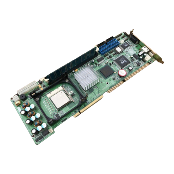
- Page 1 F u l l - size CPU Card S B C - 8 6 0 SBC-860 Rev. A Socket 478 based Intel® Pentium® 4 processor Full-size CPU Card With Integrated Intel® 82845GV chipset, DDR, 4 USBs, Dual Ethernet & CompactFlash. SBC-860 Rev. A Manual 6 Jan. 2004...
- Page 2 While reasonable efforts have been made in the preparation of this document to assure its accuracy, AAEON assumes no liabilities resulting from errors or omissions in this document, or from the use of the information contained herein.
- Page 3 F u l l - size CPU Card S B C - 8 6 0 Acknowledgments All other products’ name or trademarks are properties of their respective owners. Award is a trademark of Award Software International, Inc. CompactFlash™ is a trademark of the Compact Flash Association. Intel®...
- Page 4 S B C - 8 6 0 Packing List Before you begin installing your card, please make sure that the following materials have been shipped: • 1 SBC-860 Full-Size CPU Card • 1 Quick Installation Guide • 1 CD-ROM for manual (in PDF format), and drivers •...
-
Page 5: Table Of Contents
F u l l - size CPU Card S B C - 8 6 0 Contents Chapter 1 General Information 1.1 Introduction ..................1-2 1.2 Features.................... 1-4 1.3 Specifications................... 1-5 Chapter 2 Quick Installation Guide 2.1 Safety Precautions ................2-2 2.2 Location of Connectors and Jumpers......... - Page 6 F u l l - size CPU Card S B C - 8 6 0 2.18 ATX PWM 4P Power Connector (CN5)......... 2-17 2.19 Primary IDE Hard Drive Connector (CN6)......2-17 2.20 Serial Port COM 2 (CN7)............2-18 2.21 Serial Port COM 1 (CN8)............2-19 2.22 Secondary IDE Hard Drive Connector (CN9).......
- Page 7 F u l l - size CPU Card S B C - 8 6 0 3.2.4 Security Setup...................3-37 3.2.5 PC Health Setup................3-38 3.2.6 Clk/Voltage Setup................3-40 3.2.7 Exit Setup..................3-42 Chapter 4 Driver Installation 4.1 Installation 1..................4-3 4.2 Installation 2..................4-4 4.3 Installation 3..................
-
Page 8: Chapter 1 General Information
F u l l - s ize CPU Card S B C - 8 6 0 Chapter General Information 1- 1 Chapter 1 General Information... -
Page 9: Introduction
F u l l - s ize CPU Card S B C - 8 6 0 1.1 Introduction Introducing AAEON’ s new SBC-860, powered by Intel Pentium® 4 processor, full size form factor single board computer (SBC) with an onboard CompactFlash Type II and four USB 2.0! SBC-860 successfully deployed Intel®... - Page 10 S B C - 8 6 0 pin-headers, offering 480Mbps high-speed efficiency and value without compromising performance. Moreover, SBC-860 is also equipped with Dual Intel Ethernet controllers. One of these provides superior 1Giga Mbps networking access ability for high speed networking applications such as gateway, VPN, Mini server.
-
Page 11: Features
F u l l - s ize CPU Card S B C - 8 6 0 1.2 Features Supports Intel® Pentium® 4 mSocket 478 CPU Integrated AC-97 2.3 codec PCI 3D Audio Supports type II CompactFlash 4 USB ports onboard High Drive design to enhance the ISA driving capacity Supports H/W status monitoring Support 1 IrDA... -
Page 12: Specifications
F u l l - s ize CPU Card S B C - 8 6 0 1.3 Specifications System Supports Intel® 478 pin Pentium® 4 (400/533 MHz FSB). Chipset Intel® 82845GV Intel® 82801DB (ICH4) IO Chipset ITE-8712. Fully 16-bit I/O decoded Award 4 Mb Flash BIOS. - Page 13 F u l l - s ize CPU Card S B C - 8 6 0 jumper setting. (16C550 equivalent) Connector: Two (5x2) 2.00mm pin header Parallel port One bi-directional parallel port. Supports SPP, ECP, and EPP modes. Connector: One (13x2) 2.00mm pin header Keyboard/ PS2 A 6-pin mini-DIN connector supports PC/AT...
- Page 14 F u l l - s ize CPU Card S B C - 8 6 0 Audio One (7x2) 2.0mm pin header for Microphone In, Interface Line In/Out, CD-In Display Chipset Intel® 82845GV Share up to 8MB with Dynamic Video Memory Display Memory Technology Supports non-interlaced CRT...
- Page 15 F u l l - s ize CPU Card S B C - 8 6 0 Expansion Interface PCIMG ITE IT8888 PCI to ISA bridge ISA Bus Support 64mA high driving capability for ISA-bus High Drive slot on backplane Mechanical and Environment 13.3”(L) x 4.8”(W) Dimension 1.2lb (0.5kg)
-
Page 16: Chapter 2 Quick Installation Guide
F u l l - size CPU Card S B C - 8 6 0 Chapter Quick Installation Guide Notice: The Quick Installation Guide is derived from Chapter 2 of user manual. For other chapters and further installation instructions, please refer to the user manual CD-ROM that came with the product. -
Page 17: Safety Precautions
F u l l - size CPU Card S B C - 8 6 0 2.1 Safety Precautions Always completely disconnect the power cord from your board whenever you are working on it. Do not make connections while the power is on, because a sudden rush of power can damage sensitive electronic components. -
Page 18: Location Of Connectors And Jumpers
F u l l - size CPU Card S B C - 8 6 0 2.2 Location of Connectors and Jumpers Locating connectors and jumpers (component side) Chapter 2 Quick Installation Guide 2 - 3... - Page 19 F u l l - size CPU Card S B C - 8 6 0 Locating connector (solder side) Chapter 2 Quick Installation Guide 2 - 4...
-
Page 20: Mechanical Drawing
F u l l - size CPU Card S B C - 8 6 0 2.3 Mechanical Drawing Mechanical drawing (component side) Chapter 2 Quick Installation Guide 2 - 5... - Page 21 F u l l - size CPU Card S B C - 8 6 0 Mechanical Drawing (solder side) Chapter 2 Quick Installation Guide 2 - 6...
-
Page 22: List Of Jumpers
F u l l - size CPU Card S B C - 8 6 0 2.4 List of Jumpers The board has a number of jumpers that allow you to configure your system to suit your application. The table below shows the function of each of the jumpers of the board: Jumpers Label Function... -
Page 23: List Of Connectors
F u l l - size CPU Card S B C - 8 6 0 2.5 List of Connectors The board has a number of connectors that allow you to configure your system to suit your application. The table below shows the function of each of the connectors of the board: Connectors Label Function... - Page 24 F u l l - size CPU Card S B C - 8 6 0 CN23 Compact Flash Disk Connector CN24 External 5VSB/PWRGD Connector Chapter 2 Quick Installation Guide 2 - 9...
-
Page 25: Setting Jumpers
F u l l - size CPU Card S B C - 8 6 0 2.6 Setting Jumpers You configure your card to match the needs of your application by setting jumpers. A jumper is the simplest kind of electric switch. It consists of two metal pins and a small metal clip (often protected by a plastic cover) that slides over the pins to connect them. -
Page 26: Front Panel (Jp1)
F u l l - size CPU Card S B C - 8 6 0 2.7 Front Panel (JP1) Signal Signal Power Button HDD LED External Speaker Power LED Reset Button 2.8 COM2 RS-232/422/485 Selection – 1 (JP2) Function 1-2, 4-5, 7-8, 10-11 RS-232 (Default) 2-3, 5-6, 8-9, 11-12 RS-422... -
Page 27: Com2 Rs-232/422/485 Selection - 2 (Jp4)
F u l l - size CPU Card S B C - 8 6 0 2.10 COM2 RS-232/422/485 Selection - 2 (JP4) Function RS-232 (Default) RS-422 RS-485 2.11 CPU FSB Setting (JP5) Function CPU Auto Detect (Default) 400MHz Open 533MHz 2.12 Clear CMOS (JP6) JP11 Function... -
Page 28: Atx Power Connector (Cn1)
F u l l - size CPU Card S B C - 8 6 0 2.14 ATX Power Connector (CN1) Signal Signal 3.3 Volt. 3.3 Volt. 3.3 Volt. -12 Volt. 5 Volt. PS_ON 5 Volt. ATXPWRGD -5 Volt. 5 Volt. Stand By 5 Volt. -
Page 29: Floppy Drive Connector (Cn3)
F u l l - size CPU Card S B C - 8 6 0 2.16 Floppy Drive Connector (CN3) With two options on floppy drive you could simply adopt any of the combinations of 5.25" (360 KB and 1.2 MB) and/or 3.5" (720 KB, 1.44 MB, and 2.88 MB) drives onto the mainboard. - Page 30 F u l l - size CPU Card S B C - 8 6 0 board indicating pin number 1. Also, the connector on the floppy drive connector may have a slot. When the slot is up, pin number 1 should be on the right. Check the documentation that came with the drive for more information.
-
Page 31: Parallel Port 1 Connector (Cn4)
F u l l - size CPU Card S B C - 8 6 0 Floppy (CN3) Signal Signal DENSEL# INDEX# MTRA# DRVB# DRVA# MTRB# DIR# STEP# WDATA# WGATE# TRK0# WPT# RDATA# HDSEL# DSKCHG# 2.17 Parallel Port 1 Connector (CN4) Signal Signal STBX... -
Page 32: Atx Pwm 4P Power Connector (Cn5)
F u l l - size CPU Card S B C - 8 6 0 PTD6 PTD7 ACK# BUSY SLCT 2.18 ATX PWM 4P Power Connector (CN5) Signal +12 Volt. +12 Volt. 2.19 Primary IDE Hard Drive Connector (CN6) Signal Signal PRI_IDERST# PDD7... -
Page 33: Serial Port Com2 (Cn7)
F u l l - size CPU Card S B C - 8 6 0 PDIOR# PIORDY PDDACK# IRQ14 PDA1 P66DET PDA0 PDA2 PDCS#1 PDCS#3 IDEACTP# 2.20 Serial Port COM2 (CN7) COM 2 supports RS-232/422/485 mode, which allows you to connect serial devices (mouse, printer, etc.) COM 2/RS-232 Mode (CN7) Signal... -
Page 34: Serial Port Com1 (Cn8)
F u l l - size CPU Card S B C - 8 6 0 Signal Signal TXD- TXD+ 2.21 Serial Port COM1 (CN8) Signal Signal DCDA DTRA DSRA RTSA CTSA 2.22 Secondary IDE Hard Drive Connector(CN9) Signal Signal SEC_IDERST# SDD7 SDD8 SDD6... -
Page 35: Wake On Lan Connector (Cn10)
F u l l - size CPU Card S B C - 8 6 0 SDIOR# SIORDY SDDACK# IRQ15 SDA1 S66DET SDA0 SDA2 SDCS#1 SDCS#3 IDEACTS# 2.23 Wake on LAN Connector (CN10) Signal 5VSB RI/PCI_PME# SMBDATA SMBCLK 2.24 IrDA Connector (CN11) Signal Signal CIR_Tx... -
Page 36: Usb 2.0 Port 2 Connector (Cn12)
S B C - 8 6 0 2.25 USB 2.0 Port 2 Connector (CN12) SBC-860 provides four USB (Universal Serial Bus) interfaces, which give complete plug and play, hot attach/detach for up to 127 external devices. The USB interfaces comply with USB specification Rev. 2.0, and can be disabled in the system BIOS setup. -
Page 37: Crt Display Connector (Cn14)
F u l l - size CPU Card S B C - 8 6 0 2.27 CRT Display Connector (CN14) Signal Signal CRT_RED 5 Volt. DRT_GREEN VGA GND DRT_BLUE CRT_SDA VGA GND CRT_HSYNC VGA GND CRT_VSYNC VGA GND CRT_VSYNC VGA GND Chapter 2 Quick Installation Guide 2 - 22... -
Page 38: Ethernet 10/100/1000Baset Rj-45 Phone Jack (Cn15)
S B C - 8 6 0 2.28 Ethernet 10/100/1000 BaseT RJ-45 Phone Jack (CN15) SBC-860 supports dual 10/100 Ethernet (1 Intel 82562 Phy and 1 Lavon) or One 10/100 and one Giga bit Ethernet (1 Intel 82562 Phy and 1 Kenai-32). -
Page 39: Audio Input/Output Connector (Cn18)
F u l l - size CPU Card S B C - 8 6 0 2.30 Audio Input/Output Connector (CN18) 2 Channel Audio Output Mode (Default) Signal Signal MIC_in MIC_Vcc CD_GND LINE_in Left CD_in Left LINE_in Right CD_GND CD_in Right LINE_out Left LINE_our Right 5 Channel Audio Output Mode... -
Page 40: Mini-Din Ps/2 Connector (Cn19)
F u l l - size CPU Card S B C - 8 6 0 2.31 Mini-DIN PS/2 Connector (CN19) Signal Signal Mouse Clock Keyboard Clock Keyboard Data Mouse Data 2.32 CPU Fan Connector (CN20) Signal +12 Volt. FAN Sense 2.33 Internal Keyboard Connector (CN21) Signal Keyboard clock... -
Page 41: Internal Mouse Connector (Cn22)
F u l l - size CPU Card S B C - 8 6 0 2.34 Internal Mouse Connector (CN22) Signal Mouse clock Mouse data 2.35 Compact Flash Disk Connector (CN23) Signal Signal SDD3 SDD11 SDD4 SDD12 SDD5 SDD13 SDD6 SDD14 SDD7 SDD15... -
Page 42: External 5V Sb/Pwrgd Connector (Cn24)
F u l l - size CPU Card S B C - 8 6 0 SDA0 DASP# SDD0 PDIAG# SDD1 SDD8 SDD2 SDD9 SDD10 2.36 External 5V SB/PWRGD Connector (CN24) Signal Signal PWRGD PS_ON 5VSB Chapter 2 Quick Installation Guide 2 - 27... -
Page 43: Chapter 3 Award Bios Setup
Full size CPU Card S B C - 8 6 0 Chapter Award BIOS Setup Chapter 3 Award BIOS Setup... -
Page 44: System Test And Initialization
Full size CPU Card S B C - 8 6 0 3.1 System test and initialization These routines test and initialize board hardware. If the routines encounter an error during the tests, you will either hear a few short beeps or see an error message on the screen. - Page 45 Full size CPU Card S B C - 8 6 0 been erased. The SBC-860 CMOS memory has an integral lithium battery backup for data retention. However, you will need to replace the complete unit when it finally runs down.
-
Page 46: Award Bios Setup
Full size CPU Card S B C - 8 6 0 3.2 Award BIOS CMOS setup Awards BIOS ROM has a built-in Setup program that allows users to modify the basic system configuration. This type of information is stored in battery-backed CMOS memory so that it retains the Setup information when the power is turned off. - Page 47 Full size CPU Card S B C - 8 6 0 Advanced BIOS Features Use this menu to set the advanced features available on your system. Advanced Chipset Features Use this menu to change the values of the chipset registers and optimize your system performance. Integrated Peripherals Use this menu to specify your settings for integrated peripherals.
- Page 48 Full size CPU Card S B C - 8 6 0 Use this menu to set Supervisor/User Passwords. Clk/Voltage Setup Use this menu to specify your settings for auto detect DIMM/PCI clock and spread spectrum. PC Health Setup This menu allows you to set the shutdown temperature for your system.
-
Page 49: Main Setup
Full size CPU Card S B C - 8 6 0 3.2.1 Main Setup Standard CMOS setup Select [Main] for STANDARD CMOS SETUP option from the top menu, the screen shown below is displayed. This standard Setup Menu allows users to configure system components such as date, time, hard disk drive, floppy drive and display. - Page 50 Full size CPU Card S B C - 8 6 0 The time format is based on the 24-hour military-time clock. For example, 1 p.m. is 13:00:00 hours. Press the left or right arrow key to move to the desired field. Press the PgUp/- or PgDn/+ key to change the setting, or type the desired value into the field.
- Page 51 Full size CPU Card S B C - 8 6 0 Drive A Drive B Select the correct specifications for the diskette drive(s) installed in the computer. None N o d i s k e t t e d r i v e i n s t a l l e d 360K, 5.25 in 5- 1 / 4 i n c h P C -t y p e s t a n d a r d drive;...
- Page 52 Full size CPU Card S B C - 8 6 0 ü Base Memory Typically 640 KB. Also called conventional memory. The DOS operating system and conventional applications use this area. ü Extended Memory Above the 1-MB boundary. Early IBM personal computers could not use memory above 1 MB, but current PCs and their software can use extended memory.
-
Page 53: Advanced Features Setup
Full size CPU Card S B C - 8 6 0 3.2.2 Advanced Features Setup Advanced BIOS Features By choosing the [Advanced BIOS Feature] option from the initial setup menu, the screen below is displayed. Chapter3 Award BIOS Setup 3 - 11... - Page 54 Full size CPU Card S B C - 8 6 0 Virus Warning When enabling this item, you receive a warning message if a program (specifically, a virus) attempts to write to the boot sector or the partition table of the hard disk drive. You should then run an anti-virus program.
- Page 55 Full size CPU Card S B C - 8 6 0 The choices: Enabled, Disabled. ü First/Second/Third Boot Device The BIOS attempts to load the operating system from the devices in the sequence selected in these items. The choices: Floppy, LS120, HDD, SCSI, CDROM, ZIP100, USB-FDD, USB-ZIP, USB-CDROM, USB-HDD, LAN, ISA-FDD , Disabled.
- Page 56 Full size CPU Card S B C - 8 6 0 When Enabled, the BIOS tests (seeks) floppy drives to determine whether they have 40 or 80 tracks. Only 360-KB floppy drives have 40 tracks; drives with 720 KB, 1.2 MB, and 1.44 MB capacity all have 80 tracks. Because very few modern PCs have 40-track floppy drives, we recommend you to choose "Disabled"...
- Page 57 Full size CPU Card S B C - 8 6 0 Keystrokes repeat at a rate determined by the keyboard controller. When enabled, the typematic rate and typematic delay can be selected. The choices: Enabled/Disabled. ü Typematic Rate When the typematic rate setting is enabled, you can select a typematic rate, at which character repeats when you hold down a key.
- Page 58 S B C - 8 6 0 The choices: Enabled, Disabled ü Silent Post This feature allows you to enable the system to show AAEON’ s logo when power is on. The choices: Enabled, Disabled Chapter3 Award BIOS Setup 3 - 16...
- Page 59 Full size CPU Card S B C - 8 6 0 Advanced Chipset features setup By choosing the [Advanced Chipset Features Setup] option from the INITIAL SETUP SCREEN menu, the screen below is displayed. ü DRAM Timing Selectable This function stores information about Memory Module setting.
- Page 60 Full size CPU Card S B C - 8 6 0 specified by the system designer. The values of the choice may very with different RAM types. The choices: 1.5, 2, 2.5, 3 ü Active to Precharge Delay This function identifies the minimum active to precharge time The choices: 5, 6, 7 ü...
- Page 61 Full size CPU Card S B C - 8 6 0 ü System BIOS Cacheable Selecting Enabled allows caching of the system BIOS ROM at F0000h-FFFFFh, resulting in better system performance. The choices: Enabled, Disabled. ü Video BIOS Cacheable Selecting Enabled allows caching of the video BIOS ROM at C0000-C8000, resulting in better video performance.
- Page 62 Full size CPU Card S B C - 8 6 0 The choices: 4, 8, 16, 32, 64, 128, 256. ü On Chip VGA Setting * On-Chip VGA This allows users to select to Enable or Disable the onboard VGA function. The choices: Enabled, Disabled * On-Chip Frame Buffer Size This function is used to select the amount of main...
- Page 63 Full size CPU Card S B C - 8 6 0 Integrated Peripherals By choosing the [Integrated Peripherals] option from the INITIAL SETUP SCREEN menu, the screen below is displayed. ü IDE DMA transfer access This function to enable/disable IDE DMA transfer in DOS mode.
- Page 64 Full size CPU Card S B C - 8 6 0 The four IDE PIO (Programmable Input/Output) fields let you set a PIO mode (0-1) for each of the two IDE devices and the two storage devices that the onboard IDE interface supports. Modes 0 through 4 provide successively increased performance.
- Page 65 Full size CPU Card S B C - 8 6 0 Select Enabled when you use a Universal Serial Bus (USB) keyboard/Mouse under DOS mode. The choices: Disabled, Enabled. ü Onboard Audio/LAN 1/LAN 2 The default setting for this item is "Enabled". If you don't utilize onboard LAN / Audio funciton, just configure it as "Disabled"...
- Page 66 Full size CPU Card S B C - 8 6 0 ü Power on Function Despite the power on switch, all the devices listed below could be defined as power on methods. The choices: Any key, Button only, Keyboard 98, Password, Hot key, Mouse move, Mouse click.
- Page 67 Full size CPU Card S B C - 8 6 0 computer provides an I/O address. The more devices attached the more address needed to organize the memory storage areas. If all the I/O devices were running through the same address, your devices would come to a near halt.
- Page 68 Full size CPU Card S B C - 8 6 0 ü Onboard Parallel Port Select a logical LPT port address and corresponding interrupt for the physical parallel port. The choices: Disabled, 378/IRQ7, 278/IRQ5, 3BC/IRQ7. ü Parallel Port Mode Two bi-directional parallel ports. Supports ECP, EPP, ECP+EPP, SPP.
- Page 69 S B C - 8 6 0 Power Management Setup By choosing the [Power Management Setup] option from the INITIAL SETUP SCREEN menu, the screen below is displayed. This sample screen contains the SBC-860’ s default values for the SBC-860. ü ACPI Function This item allows you to enable/disable the Advanced Configuration and Power Interface (ACPI).
- Page 70 Full size CPU Card S B C - 8 6 0 * S3 (STR): Suspend to RAM The choices: S1 (POS), S3 (STR), S1&S3 ü Run VGA BIOS if S3 Resume This feature assigns the OS to enable/disable/auto running VGABIOS after resume from S3 mode. The choices: Yes, No, Auto ü...
- Page 71 Full size CPU Card S B C - 8 6 0 HDD Power Down =15 minutes. Max.Power Maximum power management-- ONLY Saving AVAILABLE FOR SL CPU'S. Suspend mode = 1-2 min HDD Power Down = 1 Allow you to set each mode User Defined individually.
- Page 72 Full size CPU Card S B C - 8 6 0 and possibly causing other system devices to enter power management modes. In this case the video hardware can be selected to shut off after a period of system inactivity. This determines the manner in which the monitor is blanked.
- Page 73 Full size CPU Card S B C - 8 6 0 ü HDD Power Down Disable this function or select from 1 to 15 minutes. Please refer to power management section for more information. ü Soft-Off by PWR-BTTN If you select "Instant -Off", pushing the on/off button will instantly shut down the system.
- Page 74 Full size CPU Card S B C - 8 6 0 ü Time (hh:mm:ss) Alarm ü Reload Global Timer Events When this item is enabled, an event occurring on each listed device resets the global timer to prevent the system from entering Suspend mode. These devices include: Primary/Secondary IDE 1/0, FDD/COM/LPT Port, and PCI PIRQ[A-D]#.
- Page 75 Full size CPU Card S B C - 8 6 0 PnP/PCI Configuration By choosing the PnP/PCI Configuration option from the INITIAL SETUP SCREEN menu, the screen below is displayed. ü PNP OS Installed Select Yes if the system operating environment is Plug and Play aware, for example Windows 9x, Windows 2000, and Windows XP.
- Page 76 Full size CPU Card S B C - 8 6 0 ü Reset Configuration Data Normally, you leave this field disabled. Select enabled to reset Extended System Configuration Data (ESCD) when serious conflict is caused by add-on device or system reconfiguration. The choices: Enabled, Disabled ü...
-
Page 77: Default Setup
Full size CPU Card S B C - 8 6 0 architecture. ü DMA Resources When resources are controlled manually, assign each DMA channel a type, depending on the type of device using the DMA channel. There are two types for choice: Legacy ISA and PCI/ISA PnP. - Page 78 Full size CPU Card S B C - 8 6 0 Load Optimized Defaults Select [Defaults] to Load Optimized Defaults setting from the top menu, the screen shown below is displayed. Pressing “Y” loads the default values that are factory settings for optimal performance system operations.
-
Page 79: Security Setup
Full size CPU Card S B C - 8 6 0 3.2.4 Security Setup Set/Change password You can set the password to restrict unauthorized access to enter or change the options of the setup menus. To abort the process at any time, press Esc. NOTE: To clear the password, simply press Enter when asked to enter a password. -
Page 80: Pc Health Setup
Full size CPU Card S B C - 8 6 0 3.2.5 PC Health Setup By choosing the [PC Health] option from the top menu, the screen below is displayed. Shutdown Temperature You can set the shutdown temperature. When the temperature of your system reaches the limitation, the system will shut down automatically to prevent damage caused by overheat. - Page 81 Full size CPU Card S B C - 8 6 0 speed drop down to the limitation, the system would send out the warning signal. The choices: 2000RPM, 3000RPM, 4000RPM, Disabled. Chapter3 Award BIOS Setup 3 - 39...
-
Page 82: Clk/Voltage Setup
Full size CPU Card S B C - 8 6 0 3.2.6 Clk/Voltage Setup By choosing the [Clk/Voltage] option from the top menu, the screen below is displayed. CPU Clock Ratio You may set the CPU Clock Ratio for your selection. However, if the CPU you adopts reserves no flexibility for clock ratio modification, this item will be hidden or can’... - Page 83 Full size CPU Card S B C - 8 6 0 the pulse generate excess EMI. Enabling pulse spectrum spread modulation changes the extreme pulse spikes to flat curves thus reducing EMI. This benefit may in some cases be outweighed by problems with timing-critical devices, such as a clock-sensitive SCSI device.
-
Page 84: Exit Setup
Full size CPU Card S B C - 8 6 0 3.2.7 Exit Setup Save & Exit Setup If you select this option and press <Enter> from the top menu, the values entered in the setup utilities will be recorded in the chipset’... - Page 85 F u l l - size CPU Card S B C - 8 6 0 Chapter Driver Installation Chapter 4 Driver Installation...
- Page 86 F u l l - size CPU Card S B C - 8 6 0 The SBC-860 comes with a CD-ROM which contains most of drivers and utilities of your needs. There are several installation ways depends on the driver package under different Operating System application.
- Page 87 S B C - 8 6 0 4.1 Installation 1: Applicable for Windows 2000/98/ME/NT 4.0 Insert the SBC-860 CD-ROM into the CD-ROM Drive. From the CD-ROM, select the desired component Driver folder, select the desired Operation System folder to double click on the Setup.exe icon.
- Page 88 S B C - 8 6 0 4.2 Installation 2: Applicable for Windows 2000/ 98/ME Insert the SBC-860 CD-ROM into the CD-ROM Drive. Click on Start button, select the Settings, then click on the Control Panel icon. Double click on the Add/Remove Hardware icon and Add New Hardware Wizard will appear.
- Page 89 S B C - 8 6 0 4.3 Installation 3: Applicable for Windows NT 4.0 Insert the SBC-860 CD ROM into the CD-ROM Drive. Start system with Windows NT 4.0 installed. IMPORTANT: When the "Please select the operating system to start..." message is displayed, select "Windows NT Workstation Version 4.00 [VGA mode]".
- Page 90 F u l l - size CPU Card S B C - 8 6 0 Appendix Programming the Watchdog Timer Appendix A Programming the Watchdog Timer...
-
Page 91: A.1 How To Program The Watchdog Timer
F u l l - size CPU Card S B C - 8 6 0 A.1 How to program the watchdog timer SBC-860 utilizes ITE 8712 chipset as its watchdog timer controller. Please follow the procedures below to complete its configuration. 1. Enter the MB PnP mode 2. - Page 92 F u l l - size CPU Card S B C - 8 6 0 al, 55h 2eh, al al, 55h 2eh, al ;============================ ======= ; Select logical device ;============================ ======= al, 7 ;index 7 for logical device 2eh, al al, 7 2fh, al ;============================ =======...
- Page 93 F u l l - size CPU Card S B C - 8 6 0 ;============================ ======= ; Exit the MB PnP mode ;============================ ======= al, 2 2eh, al 2fh, al Appendix A Programming the Watchdog Timer...
Need help?
Do you have a question about the SBC-860 and is the answer not in the manual?
Questions and answers